Introduction
Protection techniques are a cornerstone of reliable and safe power electronics system design. Power electronic converters operate with high voltages, high currents, fast switching speeds, and significant stored energy. These conditions make power devices such as MOSFETs, IGBTs, SCRs, and diodes highly vulnerable to abnormal events like short circuits, overloads, voltage spikes, switching transients, and thermal stress. Without proper protection, even a momentary fault can destroy expensive components, damage connected loads, or create serious safety hazards.
In real-world applications such as inverters, motor drives, switched-mode power supplies (SMPS), renewable energy systems, EV chargers, and industrial converters, faults are unavoidable. Grid disturbances, load variations, electromagnetic interference, component aging, and user mishandling all contribute to abnormal operating conditions. Protection circuits act as a safety shield, detecting faults early and either limiting the stress on components or disconnecting the system before catastrophic failure occurs.
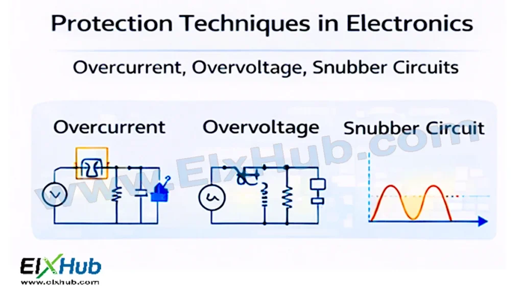
This article provides a comprehensive and practical deep dive into protection techniques used in power electronics. It covers overcurrent protection, overvoltage protection, snubber circuits, their working principles, circuit implementations, advantages, limitations, and applications. Image placeholders are included for future diagrams, and an image reference table is provided at the end for structured WordPress use and SEO optimization.
Why Protection Is Essential in Power Electronics
Power electronics systems are inherently sensitive due to fast switching and high power density. Even a small design oversight can lead to severe damage.
Key reasons protection is essential include:
- Preventing destruction of power semiconductor devices
- Protecting connected loads and users
- Ensuring system reliability and long service life
- Meeting safety standards and certifications
- Reducing maintenance and downtime costs
[Image Placeholder: Fault conditions in power electronic systems]
Without proper protection, devices may experience thermal runaway, avalanche breakdown, latch-up, or irreversible junction damage.
Common Faults in Power Electronics Systems
Understanding fault types helps in selecting appropriate protection techniques.
Electrical Faults
- Short circuits
- Overcurrent due to overload
- Overvoltage surges
- Reverse polarity
- Ground faults
Switching-Related Faults
- High dv/dt and di/dt
- Switching transients
- Voltage overshoot
- Ringing due to parasitics
Thermal Faults
- Excessive junction temperature
- Cooling system failure
- Uneven heat distribution
[Image Placeholder: Types of faults in power converters]
Overcurrent Protection Techniques
Overcurrent is one of the most dangerous faults in power electronics. Excessive current can rapidly heat devices beyond safe limits.
Causes of Overcurrent
- Short circuits at the load
- Sudden load changes
- Motor stall conditions
- Component failure
- Control circuit malfunction
Types of Overcurrent Protection
| Protection Method | Principle | Typical Applications |
|---|---|---|
| Fuse protection | Melts under excess current | Low-cost systems |
| Circuit breakers | Mechanical trip | Industrial systems |
| Current sensing + shutdown | Electronic detection | SMPS, inverters |
| Foldback current limiting | Reduces output current | Power supplies |
| Crowbar protection | Forces short circuit | Sensitive loads |
Fuse-Based Protection
Fuses are the simplest and oldest form of overcurrent protection. When current exceeds a rated value, the fuse element melts and opens the circuit.
Advantages:
- Simple and low cost
- No control circuitry required
Limitations:
- One-time use
- Slow response for fast transients
[Image Placeholder: Fuse protection in power electronics]
Electronic Overcurrent Protection
Modern power electronics systems use electronic current sensing methods.
Common current sensing techniques:
- Shunt resistors
- Hall-effect sensors
- Current transformers
- Sense-FETs
Once overcurrent is detected, the control circuit can:
- Turn off the switching device
- Reduce duty cycle
- Enter fault or latch-off mode
[Image Placeholder: Electronic current sensing circuit]
Desaturation Protection (IGBTs)
Desaturation detection is widely used for IGBTs. When an IGBT fails to turn fully on during conduction, its collector-emitter voltage rises, indicating overcurrent or short circuit.
Advantages:
- Fast response
- Protects against hard short circuits
Overvoltage Protection Techniques
Overvoltage conditions can instantly damage power semiconductor junctions.
Causes of Overvoltage
- Inductive load switching
- Lightning surges
- Grid disturbances
- Resonance and ringing
- Sudden load disconnection
Common Overvoltage Protection Methods
| Method | Operating Principle | Applications |
|---|---|---|
| TVS diodes | Voltage clamping | Low-voltage electronics |
| Zener diodes | Voltage regulation | Control circuits |
| Metal Oxide Varistors (MOVs) | Surge absorption | AC mains protection |
| Crowbar circuits | Forced short circuit | Power supplies |
| Active clamping | Controlled voltage limiting | High-speed converters |
Metal Oxide Varistors (MOVs)
MOVs are voltage-dependent resistors that clamp voltage surges.
Advantages:
- High surge energy absorption
- Fast response
Limitations:
- Degradation over time
- Not suitable for continuous overvoltage
[Image Placeholder: MOV surge protection circuit]
Transient Voltage Suppression (TVS) Diodes
TVS diodes provide precise voltage clamping and fast response, making them ideal for protecting sensitive electronics.
Applications include:
- Gate protection
- Communication interfaces
- Low-voltage power rails
Snubber Circuits in Power Electronics
Snubber circuits are critical for controlling switching transients and protecting devices from voltage and current spikes.
Why Snubbers Are Needed
Fast switching devices encounter parasitic inductance and capacitance, leading to:
- Voltage overshoot
- Ringing
- Electromagnetic interference (EMI)
- Device stress
[Image Placeholder: Switching transient waveform]
Types of Snubber Circuits
| Snubber Type | Components Used | Purpose |
|---|---|---|
| RC snubber | Resistor + Capacitor | dv/dt control |
| RCD snubber | Resistor + Capacitor + Diode | Energy dissipation |
| LC snubber | Inductor + Capacitor | Resonance suppression |
| Active snubber | Controlled switches | High efficiency |
RC Snubber Circuit
RC snubbers are commonly connected across power devices or loads.
Advantages:
- Simple design
- Effective dv/dt suppression
Limitations:
- Continuous power dissipation
- Lower efficiency
[Image Placeholder: RC snubber circuit diagram]
RCD Snubber Circuit
RCD snubbers are widely used in SMPS to clamp voltage spikes and recycle energy.
Advantages:
- Better efficiency than RC snubbers
- Reduced voltage stress
[Image Placeholder: RCD snubber in SMPS]
Snubber Design Considerations
Important factors in snubber design:
- Switching frequency
- Parasitic inductance
- Device voltage rating
- Power dissipation
Improper snubber design can increase losses or worsen EMI.
Combined Protection Strategies
In real systems, multiple protection techniques are used together.
Typical protection layers:
- Primary protection (fast electronic shutdown)
- Secondary protection (fuses, breakers)
- Tertiary protection (thermal shutdown)
[Image Placeholder: Multi-layer protection strategy]
This layered approach ensures maximum system safety.
Protection in Practical Applications
Protection techniques are essential in:
- Solar inverters
- Wind energy converters
- EV traction systems
- Motor drives
- Industrial UPS systems
| Application | Key Protection Methods |
|---|---|
| Inverters | Overcurrent, snubbers |
| Motor drives | Overcurrent, thermal |
| SMPS | Overvoltage, RCD snubber |
| EV systems | Desaturation, isolation |
Challenges and Design Trade-Offs
Designing protection circuits involves trade-offs:
- Cost vs reliability
- Speed vs complexity
- Efficiency vs robustness
Advanced power devices like SiC and GaN require even faster and more precise protection due to their high switching speeds.
Conclusion
Protection techniques are indispensable in power electronics, safeguarding devices, systems, and users from a wide range of electrical and thermal faults. Overcurrent protection prevents catastrophic heating, overvoltage protection shields devices from destructive spikes, and snubber circuits control switching transients and EMI. Together, these techniques form a comprehensive defense system that enables reliable, efficient, and safe operation of modern power electronic converters.
As power density and switching speeds continue to rise, robust protection design is no longer optional but a fundamental requirement. A well-protected power electronics system not only survives fault conditions but also delivers long-term performance, efficiency, and reliability in demanding real-world applications.
Image Reference Table
| Filename | Description | Alt Text |
|---|---|---|
| fault-conditions.png | Fault conditions in power electronics | Power electronics faults |
| fault-types.png | Electrical and switching faults | Power converter fault types |
| fuse-protection.png | Fuse-based protection circuit | Fuse overcurrent protection |
| current-sensing.png | Electronic current sensing | Overcurrent detection circuit |
| mov-protection.png | MOV surge protection | Overvoltage protection MOV |
| switching-transients.png | Switching voltage spikes | Switching transients waveform |
| rc-snubber.png | RC snubber circuit | RC snubber circuit |
| rcd-snubber.png | RCD snubber in SMPS | RCD snubber SMPS |
| protection-layers.png | Multi-layer protection | Power electronics protection layers |
SEO Title
Protection Techniques in Power Electronics – Overcurrent, Overvoltage, and Snubber Circuits
Meta Description
Learn complete protection techniques in power electronics including overcurrent protection, overvoltage protection, and snubber circuits for safe and reliable converter design.