Introduction
Power factor correction (PFC) is one of the most important concepts in modern power electronics, especially in systems connected to the AC mains. As electronic equipment has evolved, the widespread use of rectifiers, switched-mode power supplies (SMPS), motor drives, inverters, and chargers has introduced significant nonlinearity into electrical loads. These nonlinear loads draw current in pulses rather than smoothly, resulting in poor power factor, higher losses, increased heating, and reduced efficiency of power systems.
Utilities, industries, and regulatory bodies place strong emphasis on power factor because a low power factor leads to inefficient utilization of electrical infrastructure. It increases current demand for the same amount of useful power, which in turn causes higher conductor losses, transformer overloading, voltage drops, and penalties for consumers. Power factor correction techniques are therefore essential not only for compliance with standards but also for improving efficiency, reducing energy costs, and enhancing overall system reliability.
This article provides a comprehensive and practical explanation of power factor correction in electronics. It covers the fundamentals of power factor, reasons for poor power factor, passive and active PFC techniques, circuit topologies, advantages and limitations, applications, and future trends. Image placeholders are included to support diagram insertion in WordPress, and an image reference table is provided at the end for structured content management.
Understanding Power Factor
Power factor is defined as the ratio of real power to apparent power in an AC system.
Real power (P) is the actual power consumed by the load and converted into useful work, measured in watts (W).
Reactive power (Q) is the power that oscillates between the source and reactive elements such as inductors and capacitors, measured in volt-amperes reactive (VAR).
Apparent power (S) is the vector sum of real and reactive power, measured in volt-amperes (VA).
Power Factor = Real Power (W) / Apparent Power (VA)
The power factor value lies between 0 and 1. A power factor close to 1 indicates efficient utilization of electrical power.
[Image Placeholder: Power triangle showing real, reactive, and apparent power]
Causes of Low Power Factor
Low power factor occurs due to both reactive components and nonlinear current draw.
Reactive Power Effects
Inductive loads such as motors, transformers, and inductors draw lagging reactive current, reducing power factor.
Nonlinear Loads
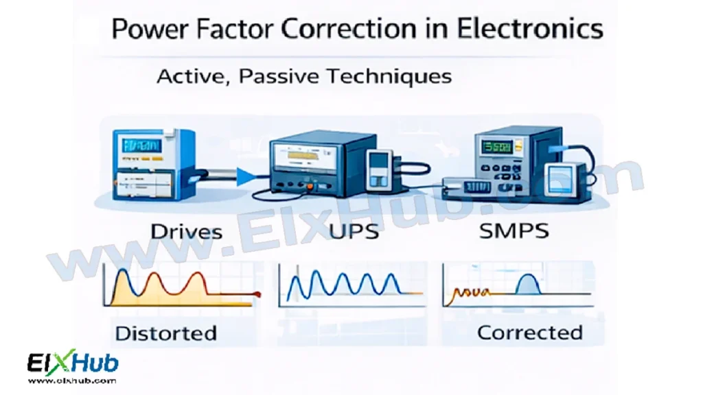
Electronic circuits using rectifiers and capacitors draw current in short pulses, causing distortion in the current waveform.
Common sources of low power factor include:
- Switched-mode power supplies
- LED drivers
- Computer power supplies
- Battery chargers
- Variable frequency drives
- Industrial inverters
[Image Placeholder: Distorted current waveform in nonlinear loads]
Effects of Poor Power Factor
Poor power factor leads to multiple technical and economic problems.
| Effect | Impact |
|---|---|
| Increased current | Higher conductor losses |
| Heating | Reduced equipment lifespan |
| Voltage drop | Poor voltage regulation |
| Transformer overloading | Reduced capacity |
| Utility penalties | Higher electricity bills |
Improving power factor reduces these negative effects significantly.
Power Factor Correction Techniques Overview
Power factor correction techniques are broadly classified into two categories:
- Passive Power Factor Correction
- Active Power Factor Correction
Each method has its own advantages, limitations, and suitable applications.
[Image Placeholder: Classification of power factor correction techniques]
Passive Power Factor Correction
Passive PFC uses passive components such as inductors and capacitors to improve power factor. It is the simplest form of correction and is commonly used in low-cost or low-power applications.
Principle of Passive PFC
Passive PFC works by adding reactive components that counteract the reactive power drawn by the load. Typically, inductors are used to smooth current waveforms, and capacitors are used to compensate for inductive reactance.
Common Passive PFC Components
| Component | Function |
|---|---|
| Inductors | Reduce current ripple |
| Capacitors | Compensate reactive power |
| LC filters | Improve waveform shape |
Passive PFC Circuits
In rectifier-based power supplies, a series inductor is placed at the input to reduce current spikes. Capacitors may also be added to compensate inductive effects.
[Image Placeholder: Passive PFC using input inductor]
Advantages of Passive PFC
- Simple design
- High reliability
- No control circuitry required
- Low electromagnetic interference (EMI)
Limitations of Passive PFC
- Bulky and heavy components
- Limited power factor improvement
- Fixed compensation (not adaptive)
- Poor performance under varying loads
Passive PFC typically achieves a power factor of around 0.7 to 0.85.
Active Power Factor Correction
Active PFC uses power electronic circuits and control techniques to actively shape the input current so that it follows the input voltage waveform. This results in near-unity power factor.
Principle of Active PFC
Active PFC circuits use a high-frequency switching converter to control the input current. By adjusting the duty cycle of the switching device, the input current is made sinusoidal and in phase with the input voltage.
[Image Placeholder: Active PFC current shaping concept]
Common Active PFC Topologies
| Topology | Description | Applications |
|---|---|---|
| Boost PFC | Most widely used | SMPS, chargers |
| Buck PFC | Step-down input voltage | Special cases |
| Buck-boost PFC | Wide input range | Universal supplies |
| Interleaved PFC | Reduced ripple | High-power systems |
Boost Converter Based PFC
The boost converter is the most common topology for active PFC. It places a boost stage after the rectifier and before the DC bus.
Key features:
- Continuous input current
- High power factor (>0.95)
- Regulated DC output voltage
[Image Placeholder: Boost PFC circuit diagram]
Control Methods in Active PFC
Active PFC circuits rely on advanced control algorithms.
Common control techniques include:
- Average current mode control
- Peak current mode control
- Voltage-mode control
- Digital control using microcontrollers or DSPs
These controllers continuously monitor input voltage and current to maintain proper phase alignment.
Comparison of Passive and Active PFC
| Parameter | Passive PFC | Active PFC |
|---|---|---|
| Complexity | Low | High |
| Cost | Low | Higher |
| Size | Large | Compact |
| Power factor | Moderate | Near unity |
| Adaptability | Fixed | Dynamic |
| Efficiency | Moderate | High |
Active PFC is preferred in modern electronic equipment due to regulatory requirements and efficiency benefits.
Power Factor Correction Standards and Regulations
Many international standards mandate minimum power factor levels.
| Standard | Requirement |
|---|---|
| IEC 61000-3-2 | Harmonic current limits |
| EN 61000 | EMC compliance |
| ENERGY STAR | High efficiency |
| 80 PLUS | PSU efficiency certification |
Active PFC is often required to meet these standards, especially for equipment above 75 W.
Applications of Power Factor Correction
Power factor correction is widely used in various industries.
| Application | PFC Type Used |
|---|---|
| Computer power supplies | Active PFC |
| LED lighting | Passive or Active |
| EV chargers | Active PFC |
| Industrial drives | Active PFC |
| Consumer electronics | Passive PFC |
[Image Placeholder: PFC in switched-mode power supply]
Design Challenges in PFC Systems
Despite its advantages, PFC design involves challenges:
- EMI and noise suppression
- Control loop stability
- Thermal management
- Cost optimization
- Component stress
Advanced simulation tools and digital control help overcome these challenges.
Future Trends in Power Factor Correction
The future of PFC technology includes:
- Digital PFC controllers
- Wide bandgap devices (SiC, GaN)
- Higher switching frequencies
- Smaller and lighter converters
- Integrated PFC and power stages
These trends aim to improve efficiency while reducing size and cost.
Conclusion
Power factor correction is an essential aspect of modern power electronics, enabling efficient, reliable, and compliant operation of electronic systems connected to AC mains. Passive PFC offers simplicity and cost-effectiveness for low-power applications, while active PFC delivers superior performance, adaptability, and near-unity power factor for high-power and regulated systems.
As energy efficiency standards become stricter and electronic loads continue to grow, the role of power factor correction will only become more significant. Understanding both passive and active PFC techniques equips engineers, students, and designers with the knowledge required to build high-performance power electronic systems that meet technical, economic, and regulatory demands.
Image Reference Table
| Filename | Description | Alt Text |
|---|---|---|
| power-triangle.png | Power triangle diagram | Real and reactive power |
| distorted-current.png | Nonlinear current waveform | Low power factor waveform |
| pfc-types.png | PFC classification diagram | Passive vs active PFC |
| passive-pfc.png | Passive PFC inductor circuit | Passive power factor correction |
| active-pfc-concept.png | Current shaping principle | Active PFC operation |
| boost-pfc.png | Boost PFC converter | Boost PFC circuit |
| pfc-smps.png | PFC in SMPS | Power factor correction in SMPS |
SEO Title
Power Factor Correction in Electronics – Active and Passive Techniques Explained
Meta Description
Learn power factor correction in electronics, including passive and active PFC techniques, circuits, advantages, standards, and real-world applications.