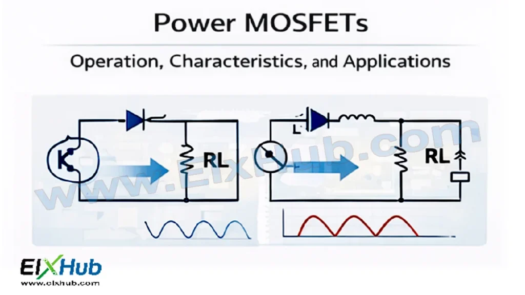
Introduction
Power MOSFETs (Metal-Oxide-Semiconductor Field-Effect Transistors) are among the most widely used semiconductor devices in modern power electronics. Their high switching speed, voltage-controlled operation, and low conduction losses make them ideal for applications ranging from DC-DC converters and inverters to motor drives and power management circuits. Unlike traditional BJTs or SCRs, MOSFETs require very little gate current to turn ON, which allows simpler driving circuits and higher efficiency in high-frequency applications.
This article provides a comprehensive guide to Power MOSFETs, covering their structure, working principles, electrical characteristics, switching behavior, and practical applications. Detailed tables, diagrams, and image placeholders are included for WordPress use to illustrate concepts such as MOSFET symbols, internal structure, switching waveforms, and typical circuit topologies.
By the end of this article, readers will understand how Power MOSFETs operate, how to select them for specific applications, and how to integrate them into high-performance power electronics circuits.
Overview of Power MOSFETs
Power MOSFETs are voltage-controlled devices with three terminals: Gate (G), Drain (D), and Source (S). Unlike BJTs, where current controls the transistor, MOSFETs use voltage applied to the gate to modulate the conduction channel between drain and source.
Key Advantages:
- Fast switching speeds (nano- to microseconds)
- Low ON-resistance, minimizing conduction losses
- High input impedance, reducing driver power requirements
- Suitable for both low and high voltage applications
[Image Placeholder: Power MOSFET symbol and terminal diagram]
MOSFETs are classified into two types based on channel conduction:
- Enhancement-mode MOSFETs: Normally OFF at zero gate voltage; conducting when gate is positively biased (N-channel) or negatively biased (P-channel).
- Depletion-mode MOSFETs: Normally ON at zero gate voltage; turned OFF by applying reverse gate voltage.
Construction and Operation
A typical power MOSFET uses a vertical structure to handle high current and voltage. The N-channel vertical MOSFET is widely used due to better electron mobility compared to holes in P-channel devices.
Working Principle:
- A positive voltage applied to the gate of an N-channel MOSFET creates an electric field that attracts electrons, forming a conductive channel between source and drain.
- The drain current is proportional to the gate voltage above the threshold voltage (V_GS(th)).
- Power MOSFETs can switch rapidly between ON and OFF states, making them ideal for high-frequency switching applications.
[Image Placeholder: Cross-sectional diagram of N-channel Power MOSFET]
Electrical Characteristics
| Parameter | Description | Typical Range |
|---|---|---|
| V_DS (Drain-Source Voltage) | Maximum voltage between drain and source | 30V – 1200V |
| I_D (Drain Current) | Maximum continuous drain current | 1A – 100A+ |
| R_DS(on) | On-state resistance | 5 mΩ – 500 mΩ |
| V_GS(th) | Gate threshold voltage | 2V – 6V |
| C_iss, C_oss, C_rss | Input, output, reverse transfer capacitances | Vary by device, important for switching frequency |
| Switching times | Rise, fall, turn-on, turn-off | Nano- to microseconds |
Understanding these parameters is critical for designing efficient circuits and avoiding thermal or electrical overstress.
Switching Behavior
Power MOSFETs are ideal for high-frequency switching due to their fast turn-on and turn-off characteristics. Switching losses and gate drive requirements must be considered in practical circuits.
Turn-On:
- Gate voltage rises above V_GS(th)
- Drain current increases
- Voltage drop across MOSFET decreases to R_DS(on) × I_D
Turn-Off:
- Gate voltage is removed
- Channel conductivity ceases
- Drain voltage rises to supply level
[Image Placeholder: MOSFET switching waveform diagram]
Proper gate drive circuitry ensures minimal switching losses and prevents oscillations caused by parasitic inductances and capacitances.
Power MOSFET Configurations
Single MOSFET Switch
Used in simple DC load control or low-power DC-DC converters. The MOSFET acts as a high-speed switch.
[Image Placeholder: Single MOSFET switch circuit diagram]
Half-Bridge and Full-Bridge Configurations
Essential for inverters, motor drives, and SMPS applications. Two or four MOSFETs are arranged to provide bidirectional current control and voltage conversion.
[Image Placeholder: Half-bridge and full-bridge MOSFET circuits]
Synchronous Rectification
In DC-DC converters, MOSFETs replace diodes for low-voltage, high-current applications to reduce conduction losses.
[Image Placeholder: Synchronous rectifier MOSFET diagram]
Thermal Management
Power MOSFETs dissipate heat during conduction and switching. Thermal design considerations include:
- Heatsinks and thermal pads
- Forced air or liquid cooling for high-power applications
- Proper PCB layout to reduce thermal resistance
| Parameter | Recommended Practice |
|---|---|
| Junction Temperature (Tj) | Keep below 150°C |
| PCB copper area | Increase width and layers for heat dissipation |
| Heatsink | Match Rth junction-case for device rating |
| Thermal grease | Improve thermal contact |
[Image Placeholder: MOSFET with heatsink illustration]
Protection Techniques
MOSFETs are susceptible to overcurrent, overvoltage, and overheating. Protection methods include:
- Gate resistors to limit inrush current during switching
- TVS diodes for transient voltage protection
- Current sense resistors for overcurrent detection
- Soft-start circuits to limit inrush power
[Image Placeholder: MOSFET protection circuit diagram]
Applications of Power MOSFETs
Power MOSFETs are highly versatile and widely used in:
- DC-DC converters (buck, boost, buck-boost)
- High-efficiency inverters for solar and UPS systems
- Motor drives for electric vehicles and industrial applications
- Synchronous rectifiers in switch-mode power supplies
- Class-D audio amplifiers for high-efficiency audio power delivery
| Application | Configuration | Notes |
|---|---|---|
| DC-DC converter | Single MOSFET or synchronous MOSFET | Efficient voltage step-down or step-up |
| Motor drive | Half-bridge or full-bridge | PWM control for speed regulation |
| Solar inverter | Full-bridge | Converts DC from PV panels to AC |
| UPS system | MOSFET bridge | Fast switching and low losses |
| Audio amplifier | MOSFET Class-D | High efficiency, low heat generation |
Master Selection: Need help choosing? See our Ultimate MOSFET Selection Guide.
Conclusion
Power MOSFETs have become the cornerstone of modern power electronics due to their high-speed switching, low ON-resistance, and voltage-controlled operation. Proper understanding of their structure, electrical characteristics, switching behavior, and thermal management is critical for designing reliable and efficient circuits. From DC-DC converters and inverters to motor drives and audio amplifiers, MOSFETs offer unparalleled performance in both industrial and consumer applications.
Image Reference Table
| Filename | Description | Alt Text |
|---|---|---|
| mosfet-symbol.png | Power MOSFET symbol and terminals | Power MOSFET symbol |
| mosfet-crosssection.png | Cross-sectional N-channel MOSFET structure | MOSFET internal structure |
| mosfet-switching.png | MOSFET turn-on and turn-off waveforms | MOSFET switching behavior |
| mosfet-single-switch.png | Single MOSFET switch circuit | Single MOSFET switching circuit |
| mosfet-half-full-bridge.png | Half-bridge and full-bridge MOSFET circuits | MOSFET bridge circuits |
| mosfet-synchronous.png | Synchronous rectifier MOSFET diagram | Synchronous rectifier |
| mosfet-heatsink.png | MOSFET with heatsink illustration | MOSFET thermal management |
| mosfet-protection.png | MOSFET protection circuit diagram | MOSFET overcurrent and voltage protection |
| mosfet-application.png | MOSFET in DC-DC converter and motor drive | MOSFET practical applications |
SEO Title
Power MOSFETs – Operation, Switching, Characteristics, and Applications in Power Electronics
Meta Description
Explore Power MOSFETs for high-speed switching, low-loss operation, applications in DC-DC converters, inverters, motor drives, and protection techniques in power electronics circuits.