Introduction
AC-DC converters, commonly known as rectifiers, are fundamental building blocks in power electronics. Almost every electronic system, from small battery chargers to large industrial power supplies, relies on rectification to convert alternating current (AC) into direct current (DC). Since most power generation and transmission systems supply AC, while electronic circuits typically require DC, rectifiers form the essential interface between the power grid and electronic loads.
Rectifiers are used in consumer electronics, power adapters, battery charging systems, industrial DC drives, electroplating units, welding equipment, and high-voltage DC transmission systems. Understanding rectifier operation is crucial for anyone studying or working in power electronics because rectification is the first stage in most power conversion chains.
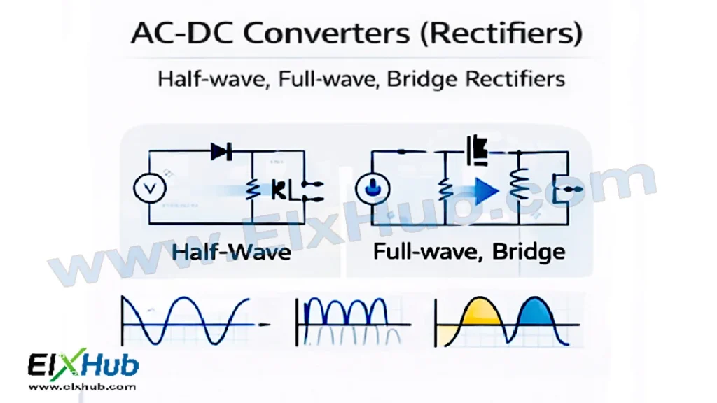
This article provides a complete and practical explanation of AC-DC converters, focusing on half-wave, full-wave (center-tapped), and bridge rectifiers. It covers their working principles, circuit operation, waveforms, performance parameters, advantages, limitations, and real-world applications. Image placeholders are included for circuit diagrams and waveforms, along with an image reference table at the end for future content management.
What is Rectification?
Rectification is the process of converting alternating current, which periodically changes direction, into unidirectional current that flows in only one direction. The output of a rectifier is not perfectly smooth DC; instead, it is a pulsating DC that usually requires filtering and regulation to become suitable for electronic circuits.
The key element used in rectifiers is the power diode. A diode allows current to flow in one direction (forward bias) and blocks it in the opposite direction (reverse bias). By arranging diodes appropriately, different rectifier configurations can be created to utilize one or both halves of the AC input waveform.
[Image Placeholder: Basic concept of AC waveform converted to pulsating DC]
Classification of Rectifiers
Rectifiers can be broadly classified based on how much of the AC waveform they utilize:
| Rectifier Type | AC Cycle Used | Number of Diodes |
|---|---|---|
| Half-wave rectifier | One half-cycle | 1 |
| Full-wave rectifier (center-tapped) | Both half-cycles | 2 |
| Bridge rectifier | Both half-cycles | 4 |
Each type has distinct characteristics, efficiency levels, cost implications, and application areas.
Half-Wave Rectifier
Circuit Description
A half-wave rectifier is the simplest form of AC-DC converter. It uses a single diode connected in series with a load resistor and an AC source, typically via a transformer.
[Image Placeholder: Half-wave rectifier circuit diagram]
Working Principle
During the positive half-cycle of the AC input, the diode becomes forward-biased and conducts current through the load. During the negative half-cycle, the diode is reverse-biased and blocks current, resulting in no output across the load.
As a result, only one half of the AC waveform appears across the load, producing a pulsating DC output.
[Image Placeholder: Input and output waveforms of half-wave rectifier]
Key Characteristics
| Parameter | Description |
|---|---|
| Output waveform | Pulsating DC |
| Ripple frequency | Same as input frequency |
| Rectification efficiency | Low |
| Ripple factor | High |
| Transformer utilization | Poor |
Advantages
- Simple circuit design
- Low cost
- Minimal components
Limitations
- Very low efficiency
- High ripple content
- Poor voltage regulation
- Not suitable for high-power applications
Applications
Half-wave rectifiers are mainly used for educational purposes and very low-power applications where performance is not critical, such as simple signal rectification or demonstration circuits.
Full-Wave Rectifier (Center-Tapped)
Circuit Description
A full-wave rectifier uses two diodes and a center-tapped transformer. The center tap acts as a reference point, allowing each diode to conduct during alternate half-cycles of the AC input.
[Image Placeholder: Full-wave center-tapped rectifier circuit diagram]
Working Principle
During the positive half-cycle of the input AC, one diode conducts and supplies current to the load. During the negative half-cycle, the other diode conducts, again supplying current to the load in the same direction.
Thus, both halves of the AC waveform are utilized, resulting in a smoother DC output compared to a half-wave rectifier.
[Image Placeholder: Input and output waveforms of full-wave rectifier]
Key Characteristics
| Parameter | Description |
|---|---|
| Output waveform | Pulsating DC (both half-cycles) |
| Ripple frequency | Twice the input frequency |
| Rectification efficiency | Higher than half-wave |
| Ripple factor | Lower than half-wave |
| Transformer requirement | Center-tapped |
Advantages
- Better efficiency than half-wave rectifier
- Reduced ripple content
- Improved output voltage utilization
Limitations
- Requires a center-tapped transformer
- Higher transformer cost and size
- Increased complexity compared to half-wave
Applications
Full-wave rectifiers are used in medium-power DC supplies, audio amplifiers, and laboratory power units where improved efficiency and reduced ripple are needed.
Bridge Rectifier
Circuit Description
A bridge rectifier uses four diodes arranged in a bridge configuration. It does not require a center-tapped transformer, making it more compact and cost-effective for many applications.
[Image Placeholder: Bridge rectifier circuit diagram]
Working Principle
During the positive half-cycle of the AC input, two diodes conduct and allow current to flow through the load. During the negative half-cycle, the other two diodes conduct, again allowing current to flow through the load in the same direction.
As a result, both halves of the AC waveform contribute to the output, similar to a full-wave rectifier, but without the need for a center-tapped transformer.
[Image Placeholder: Bridge rectifier input and output waveforms]
Key Characteristics
| Parameter | Description |
|---|---|
| Number of diodes conducting | Two at a time |
| Ripple frequency | Twice the input frequency |
| Transformer utilization | High |
| Voltage drop | Slightly higher due to two diode drops |
Advantages
- No center-tapped transformer required
- Better transformer utilization
- Compact and economical
- Widely used in practical power supplies
Limitations
- Slightly higher conduction losses
- More diodes compared to center-tapped design
Applications
Bridge rectifiers are the most commonly used rectifiers in:
- Power adapters
- Battery chargers
- SMPS front-end rectification
- Consumer electronics
Comparison of Rectifier Types
| Feature | Half-Wave | Full-Wave (CT) | Bridge |
|---|---|---|---|
| Efficiency | Low | Medium | High |
| Ripple | Very high | Medium | Low |
| Diodes used | 1 | 2 | 4 |
| Transformer | Simple | Center-tapped | Simple |
| Cost | Lowest | Higher | Moderate |
| Practical use | Rare | Limited | Very common |
Performance Parameters of Rectifiers
Ripple Factor
Ripple factor measures the amount of AC content present in the rectifier output. Lower ripple factor indicates smoother DC output.
Rectification Efficiency
Efficiency indicates how effectively AC power is converted into DC power. Full-wave and bridge rectifiers have significantly higher efficiency than half-wave rectifiers.
Peak Inverse Voltage (PIV)
PIV is the maximum reverse voltage that a diode must withstand. Bridge rectifiers generally require diodes with lower PIV ratings compared to center-tapped full-wave rectifiers.
[Image Placeholder: Peak inverse voltage illustration in rectifier circuits]
Filters Used with Rectifiers
Since rectifier output is pulsating DC, filters are used to smooth the output. Common filter types include:
- Capacitor filters
- Inductor filters
- LC filters
- RC filters
[Image Placeholder: Rectifier with capacitor filter circuit]
Filtering significantly reduces ripple and improves DC quality for electronic loads.
Practical Considerations in Rectifier Design
| Aspect | Design Consideration |
|---|---|
| Diode rating | Current and voltage margin |
| Heat dissipation | Adequate heatsinking |
| Transformer rating | Proper VA capacity |
| Load variation | Regulation requirements |
| Safety | Isolation and fusing |
Proper component selection ensures reliability and long service life of rectifier-based power supplies.
Applications of AC-DC Converters
Rectifiers are used in nearly every electrical and electronic system:
- DC power supplies
- Battery charging systems
- DC motor drives
- Electroplating and electrolysis
- Welding machines
- HVDC transmission (with controlled rectifiers)
Conclusion
AC-DC converters form the foundation of power electronics by enabling the conversion of AC power into usable DC power. Half-wave rectifiers offer simplicity but poor performance, making them suitable mainly for educational purposes. Full-wave rectifiers improve efficiency and output quality but require center-tapped transformers. Bridge rectifiers provide the best balance of performance, cost, and practicality, making them the most widely used rectifier configuration in modern electronic systems.
A solid understanding of rectifier types, working principles, waveforms, and design considerations is essential for designing reliable power supplies and power electronic systems.
Image Reference Table
| Filename | Description | Alt Text |
|---|---|---|
| ac-to-dc-concept.png | AC to DC conversion concept | AC to DC conversion |
| half-wave-rectifier-circuit.png | Half-wave rectifier circuit | Half-wave rectifier |
| half-wave-waveform.png | Half-wave rectifier waveform | Half-wave rectifier output |
| full-wave-rectifier-ct.png | Full-wave center-tapped rectifier | Full-wave rectifier |
| full-wave-waveform.png | Full-wave rectifier waveform | Full-wave rectifier output |
| bridge-rectifier-circuit.png | Bridge rectifier circuit | Bridge rectifier |
| bridge-rectifier-waveform.png | Bridge rectifier waveform | Bridge rectifier output |
| rectifier-piv.png | Peak inverse voltage illustration | Rectifier PIV |
| rectifier-filter.png | Rectifier with filter circuit | Rectifier filter |
SEO Title
AC-DC Converters (Rectifiers) – Half-Wave, Full-Wave, and Bridge Rectifiers Explained
Meta Description
Learn AC-DC converters in power electronics, including half-wave, full-wave, and bridge rectifiers, with working principles, circuits, waveforms, advantages, and applications.