Introduction
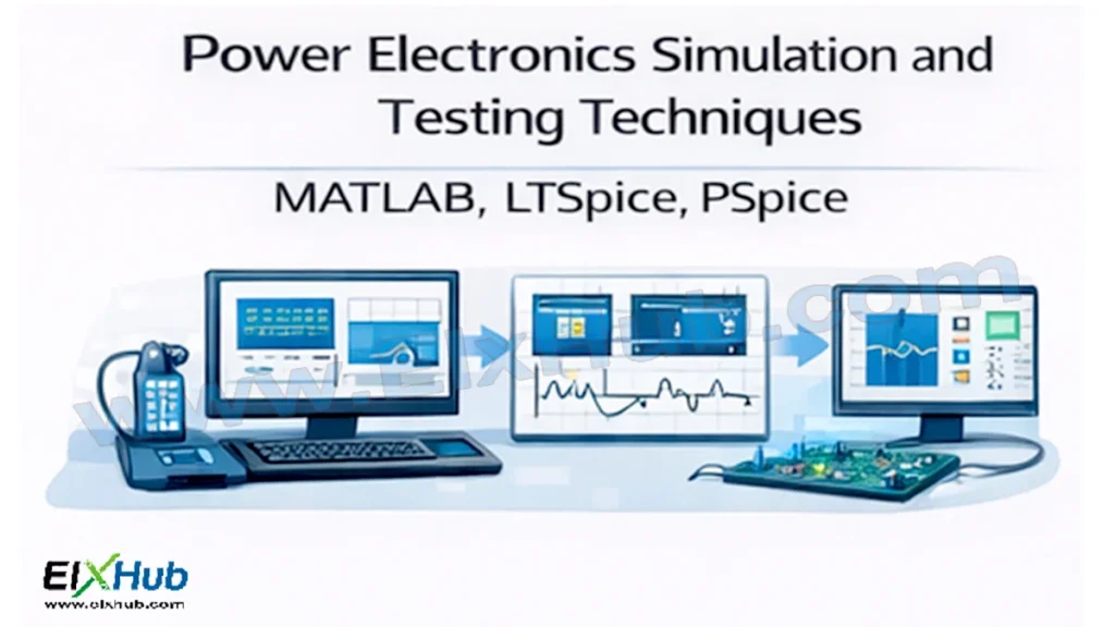
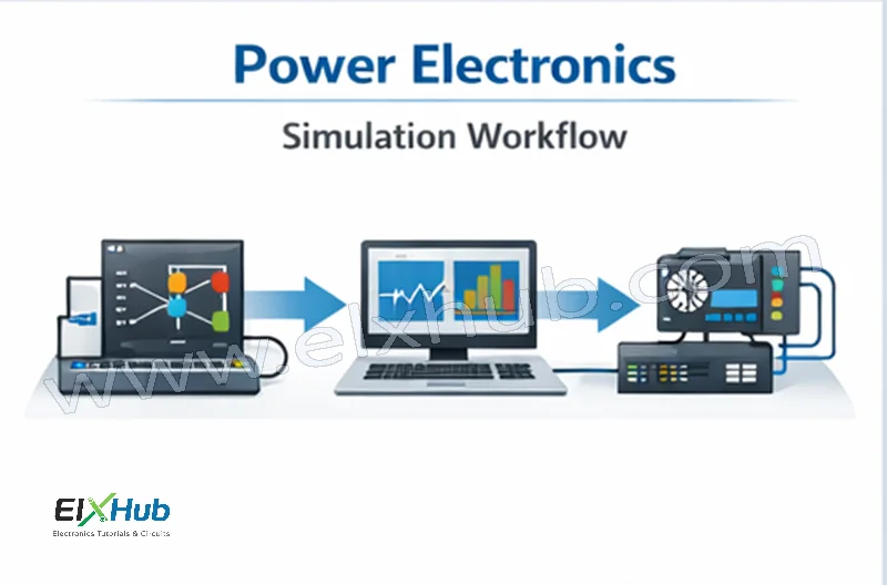
Power electronics systems are often complex, high-power, and safety-critical. Designing and testing such systems directly on hardware without prior validation can lead to component failure, high costs, safety hazards, and long development cycles. This is why simulation and testing techniques play a crucial role in modern power electronics design. Before building real converters, engineers rely on simulation tools to verify circuit behavior, analyze waveforms, estimate losses, validate control strategies, and detect faults early.
Simulation tools such as MATLAB/Simulink, LTSpice, and PSpice allow engineers to model power semiconductor devices, passive components, control loops, and thermal effects with high accuracy. These tools help bridge the gap between theoretical design and practical implementation. In this article, we will explore the importance of simulation in power electronics, understand how MATLAB, LTSpice, and PSpice are used, compare their strengths, and discuss real-world testing and validation techniques used after simulation.
Why Simulation Is Essential in Power Electronics
Power electronics circuits involve high voltages, high currents, and fast switching transitions. Testing such systems directly can be risky and expensive. Simulation provides a safe and efficient environment to analyze system behavior.
Key reasons simulation is essential include:
- Reducing design errors before hardware implementation
- Predicting voltage, current, and power waveforms
- Analyzing switching losses and efficiency
- Studying transient and steady-state behavior
- Evaluating control algorithms
- Minimizing hardware damage and development cost
Simulation also allows rapid design iteration, enabling engineers to optimize performance before finalizing hardware.
Types of Simulations in Power Electronics
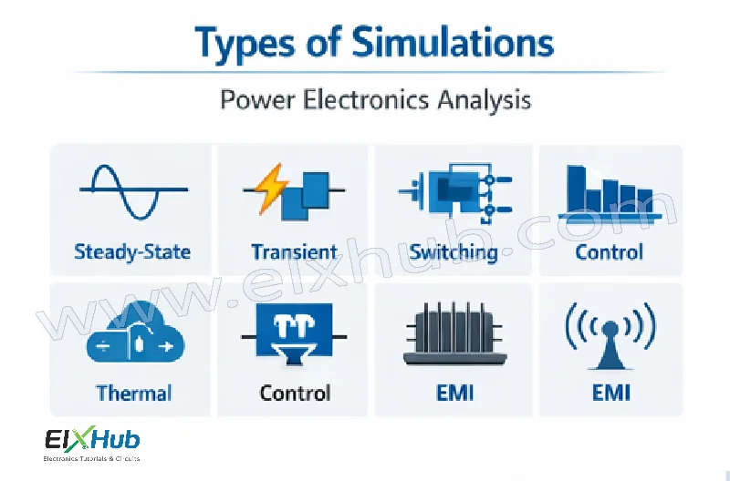
Power electronics simulations can be broadly classified into several categories.
| Simulation Type | Purpose |
|---|---|
| Steady-State Simulation | Analyze normal operating conditions |
| Transient Simulation | Study startup, shutdown, and fault conditions |
| Switching Simulation | Analyze switching behavior and losses |
| Control Simulation | Validate control algorithms |
| Thermal Simulation | Predict device temperature rise |
| EMI Simulation | Evaluate noise and interference |
MATLAB and Simulink for Power Electronics
Overview of MATLAB/Simulink
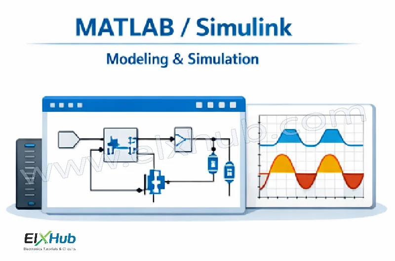
MATLAB is a numerical computing environment, while Simulink is a graphical modeling tool integrated with MATLAB. Together, they provide a powerful platform for modeling, simulation, and control of power electronic systems.
The Simscape Electrical toolbox (formerly SimPowerSystems) is specifically designed for power electronics and electrical systems.
Key Features of MATLAB/Simulink
- Block-based modeling
- Accurate semiconductor models
- Integrated control system design
- Easy visualization of waveforms
- Support for multi-domain simulation
Power Electronics Components in Simulink
Simulink provides ready-made blocks for:
- Diodes, SCRs, TRIACs
- MOSFETs and IGBTs
- Rectifiers and inverters
- DC-DC converters
- PWM generators
- Motor models
| Component | Available in Simulink |
|---|---|
| SCR | Yes |
| MOSFET | Yes |
| IGBT | Yes |
| Inverter | Yes |
| DC Motor | Yes |
| AC Motor | Yes |
Example Applications in MATLAB
MATLAB is widely used for:
- DC-DC converter modeling
- Inverter and PWM analysis
- Motor drive simulation
- Power factor correction systems
- Renewable energy systems
Advantages of MATLAB for Power Electronics
- Excellent for control system design
- Ideal for system-level modeling
- Strong visualization tools
- Supports code generation for real-time controllers
Limitations of MATLAB
- Requires powerful hardware
- Higher licensing cost
- Less detailed device-level switching compared to SPICE
LTSpice for Power Electronics Simulation
Overview of LTSpice
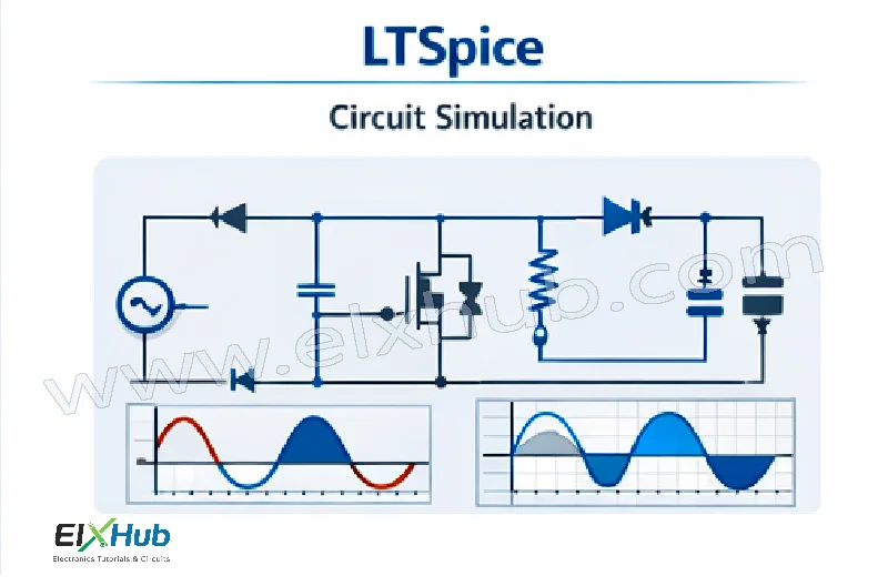
LTSpice is a free, high-performance SPICE-based simulator developed by Analog Devices. It is widely used for detailed circuit-level simulation of power electronics due to its speed and accuracy.
LTSpice is particularly strong in switching power supply design.
Key Features of LTSpice
- Fast transient simulation
- Accurate switching behavior
- Extensive component library
- Ideal for SMPS and converter design
- Free to use
Typical Power Electronics Applications in LTSpice
- SMPS design
- Buck, boost, and buck-boost converters
- Flyback and forward converters
- Snubber circuit analysis
- Gate drive design
| Application | Suitability |
|---|---|
| SMPS | Excellent |
| DC-DC converters | Excellent |
| Control algorithms | Limited |
| Large systems | Moderate |
Advantages of LTSpice
- Very fast simulation speed
- Accurate device-level modeling
- Excellent for switching analysis
- No licensing cost
Limitations of LTSpice
- Limited control system modeling
- Not ideal for large system-level simulations
- Less intuitive for beginners
PSpice for Power Electronics
Overview of PSpice
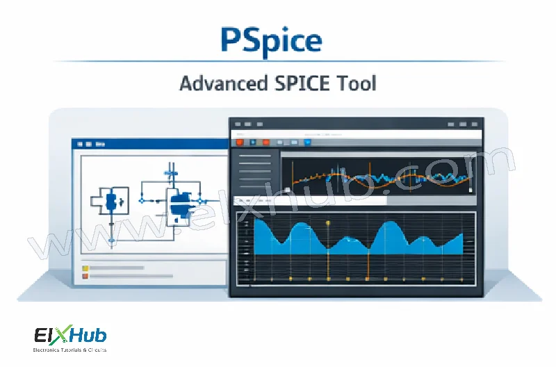
PSpice is a professional SPICE-based simulation tool widely used in academia and industry. It offers advanced modeling capabilities and supports complex power electronic systems.
PSpice is often used for device-level and circuit-level validation.
Key Features of PSpice
- Advanced semiconductor models
- Support for mixed-signal simulation
- Detailed waveform analysis
- Industrial-grade accuracy
Power Electronics Use Cases in PSpice
- SCR and TRIAC circuit simulation
- Power amplifier testing
- Motor drive circuits
- EMI and noise analysis
| Feature | PSpice Capability |
|---|---|
| SCR modeling | High |
| Mixed signal | Supported |
| Noise analysis | Advanced |
| Control design | Moderate |
Advantages of PSpice
- Highly accurate models
- Suitable for professional validation
- Strong waveform analysis tools
Limitations of PSpice
- Paid licensing
- Steeper learning curve
- Slower than LTSpice for large switching circuits
Comparison of MATLAB, LTSpice, and PSpice
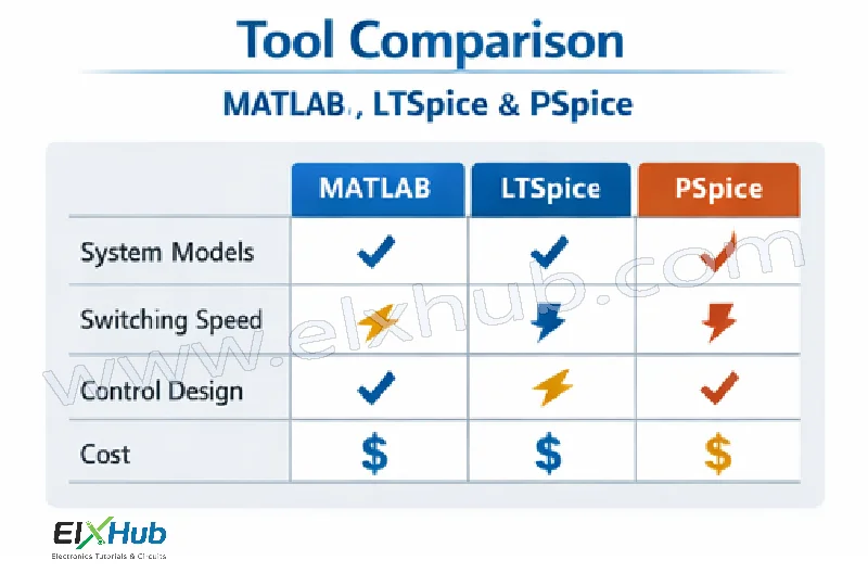
| Feature | MATLAB/Simulink | LTSpice | PSpice |
|---|---|---|---|
| System-level modeling | Excellent | Limited | Moderate |
| Switching accuracy | Moderate | Excellent | Excellent |
| Control design | Excellent | Poor | Moderate |
| Cost | High | Free | High |
| Ease of use | High | Moderate | Moderate |
Hardware Testing Techniques After Simulation
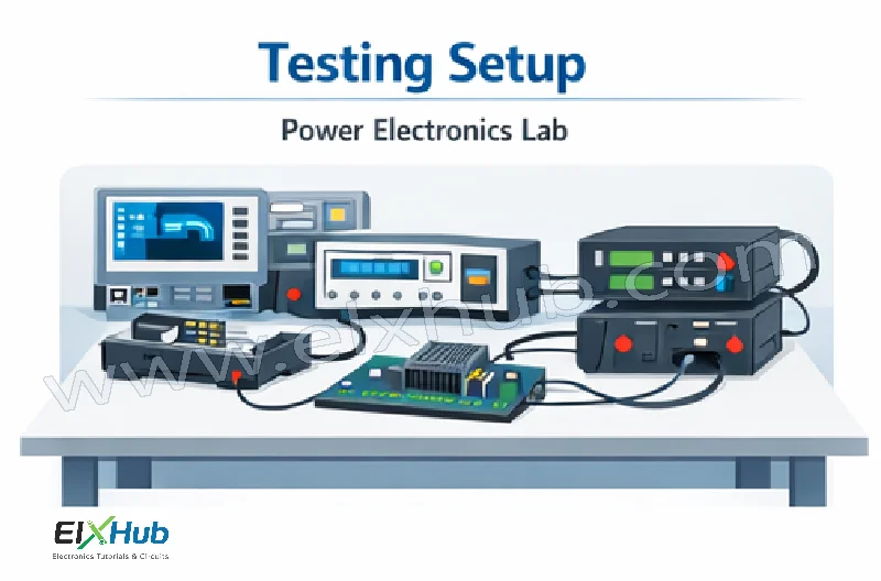
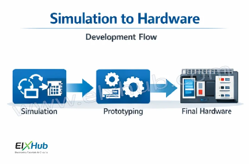
Simulation must always be followed by practical testing.
Prototyping
- Breadboard testing (low power)
- PCB prototypes
- Modular testing approach
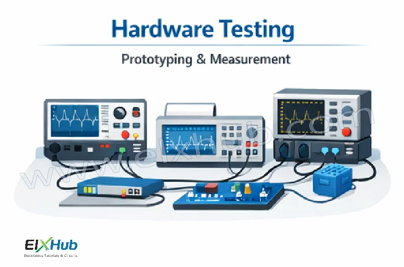
Measurement Tools
| Tool | Purpose |
|---|---|
| Oscilloscope | Voltage and current waveforms |
| Power Analyzer | Efficiency measurement |
| Multimeter | Basic measurements |
| Current Probe | High-current analysis |
| Thermal Camera | Heat distribution |
Safety Precautions During Testing
- Use isolation transformers
- Start with low voltage
- Use current limiting
- Wear protective equipment
- Ensure proper grounding
Validation and Debugging Techniques
Common validation steps include:
- Comparing simulated and measured waveforms
- Verifying switching frequency
- Checking thermal performance
- Testing under load variations
- Fault testing (short circuit, overload)
Common Simulation Mistakes to Avoid
- Ignoring parasitic components
- Incorrect gate drive modeling
- Using ideal components only
- Not considering thermal effects
- Overlooking EMI issues
Including realistic component models improves simulation accuracy.
Role of Simulation in Modern Power Electronics Design
Simulation is now an integral part of:
- Industrial converter design
- Electric vehicle powertrains
- Renewable energy systems
- Smart grid development
- Research and education
Simulation reduces development time and ensures reliable operation in real-world conditions.
Conclusion
Simulation and testing techniques are indispensable in power electronics design. Tools such as MATLAB, LTSpice, and PSpice enable engineers to analyze, optimize, and validate complex power electronic systems before hardware implementation. MATLAB excels in control and system-level modeling, LTSpice offers unmatched speed and accuracy for switching circuits, and PSpice provides professional-grade validation. When combined with proper hardware testing and safety practices, these tools ensure reliable, efficient, and robust power electronic designs. Mastery of simulation and testing techniques is a critical skill for every power electronics engineer.
SEO Title
Power Electronics Simulation and Testing – MATLAB, LTSpice, and PSpice Explained
Meta Description
Learn power electronics simulation and testing techniques using MATLAB, LTSpice, and PSpice, including design validation, comparison, and practical testing methods.