Introduction
Resistors are among the most fundamental and widely used components in electronics. From the simplest hobby circuits to advanced industrial systems, resistors play a critical role in controlling electrical behavior. They are essential for limiting current, dividing voltage, protecting sensitive components, setting biasing conditions, and shaping signals. Without resistors, modern electronic circuits would be unstable, unsafe, and largely unusable.
In basic electronics, resistors are often the first component learners encounter because they directly demonstrate the relationship between voltage, current, and resistance. Their behavior is predictable, governed mainly by Ohm’s Law, which makes them ideal for understanding how electrical energy is controlled within a circuit. Despite their simplicity, resistors come in many types, materials, constructions, and ratings, each suited for specific applications.
This article provides a complete beginner-friendly yet technically solid explanation of resistors. You will learn what resistors are, how they work, why they are needed, their symbols, construction, working principle, different types, practical uses, and how to select the right resistor for a given application.
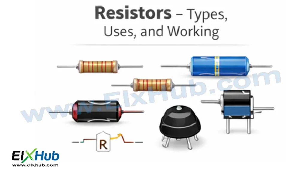
[Image Placeholder: Various types of resistors arranged with circuit symbols]
What Is a Resistor?
A resistor is a passive electronic component designed to oppose the flow of electric current. This opposition to current is known as resistance and is measured in ohms (Ω). When current flows through a resistor, electrical energy is converted into heat due to collisions between moving electrons and the atoms of the resistive material.
Resistors do not generate energy, amplify signals, or store charge. Instead, they control and manage electrical energy within a circuit. Because of this, they are classified as passive components.
In circuit diagrams, a resistor is typically represented by a zigzag symbol (common in American standards) or a rectangular box (used in IEC standards).
[Image Placeholder: Resistor circuit symbol and real resistor comparison]
Why Resistors Are Needed in Electronic Circuits
Resistors serve multiple essential purposes in electronics. Some of the most important reasons resistors are used include:
They limit current to prevent damage to components such as LEDs, transistors, and integrated circuits.
They divide voltage to obtain desired voltage levels from a single power source.
They establish biasing conditions for transistors and amplifiers.
They pull signals up or down to defined logic levels in digital circuits.
They dissipate excess power safely as heat.
They help shape waveforms in timing and filtering circuits.
Without resistors, even a simple battery-and-LED circuit could destroy the LED due to excessive current.
[Image Placeholder: LED circuit showing current-limiting resistor]
Working Principle of a Resistor
The working of a resistor is based on the principle of electrical resistance. When a voltage is applied across a resistor, an electric field is created, causing electrons to drift through the material. The resistive material offers opposition to this flow due to atomic structure and impurities.
This behavior is described by Ohm’s Law:
Voltage = Current × Resistance
As resistance increases, current decreases for a given voltage. Conversely, reducing resistance allows more current to flow.
The electrical energy lost by electrons as they move through the resistor is converted into heat. This is why resistors warm up during operation, especially in high-current or high-power applications.
[Image Placeholder: Electron flow through resistive material illustration]
Construction of Resistors
The construction of a resistor depends on its type, material, and intended application. However, most resistors share some common elements:
A resistive element made of carbon, metal, metal oxide, or wire.
Leads or terminals for electrical connection.
An insulating body or coating to protect the resistive element and provide mechanical strength.
Fixed resistors typically have a solid construction with a predefined resistance value, while variable resistors include a movable contact to change resistance.
[Image Placeholder: Internal construction of a resistor diagram]
Classification of Resistors
Resistors can be broadly classified into two main categories:
Fixed Resistors
Variable Resistors
Each category contains several subtypes designed for specific electrical, mechanical, and environmental requirements.
[Image Placeholder: Classification chart of resistor types]
Fixed Resistors
Fixed resistors have a constant resistance value that cannot be adjusted during normal operation. These are the most commonly used resistors in electronic circuits.
Carbon Composition Resistors
Carbon composition resistors are made from a mixture of carbon powder and a binding material. They were widely used in early electronics but are less common today due to lower accuracy and stability.
They are inexpensive and can withstand short-duration overloads but have higher noise and wider tolerance.
[Image Placeholder: Carbon composition resistor]
Carbon Film Resistors
Carbon film resistors are manufactured by depositing a thin layer of carbon onto a ceramic substrate. The resistance value is adjusted by cutting a spiral groove into the carbon layer.
They offer better stability, lower noise, and tighter tolerance than carbon composition resistors.
[Image Placeholder: Carbon film resistor with color bands]
Metal Film Resistors
Metal film resistors use a thin metal layer as the resistive element. They provide high accuracy, low noise, and excellent temperature stability.
These resistors are widely used in precision and low-noise applications such as audio circuits and measurement equipment.
[Image Placeholder: Metal film resistor]
Metal Oxide Film Resistors
Metal oxide resistors are similar to metal film resistors but use metal oxide instead of pure metal. They can operate at higher temperatures and withstand higher surge currents.
They are commonly used in power supplies and high-voltage applications.
[Image Placeholder: Metal oxide resistor]
Wirewound Resistors
Wirewound resistors are constructed by winding a metal wire around an insulating core. They are capable of handling high power and high current.
Due to their inductive nature, they are not suitable for high-frequency applications but are ideal for power circuits.
[Image Placeholder: Wirewound resistor]
Variable Resistors
Variable resistors allow adjustment of resistance value and are used where tuning or calibration is required.
Potentiometers
Potentiometers have three terminals and are commonly used as voltage dividers. They are widely used in volume controls, brightness controls, and adjustable reference circuits.
[Image Placeholder: Rotary potentiometer]
Rheostats
Rheostats are high-power variable resistors with two terminals. They are mainly used to control current in applications such as motor speed control and heating elements.
[Image Placeholder: Rheostat]
Trimmers and Preset Resistors
Trimmers are small adjustable resistors used for fine calibration on printed circuit boards. They are usually set once and left unchanged.
[Image Placeholder: Trimmer resistor]
Special Purpose Resistors
Some resistors are designed to change resistance based on external conditions.
Thermistors
Thermistors change resistance with temperature. They are used for temperature sensing, compensation, and protection.
[Image Placeholder: Thermistor]
Light Dependent Resistors (LDR)
LDRs change resistance based on light intensity. They are commonly used in light-sensing applications such as automatic street lights.
[Image Placeholder: LDR]
Varistors
Varistors change resistance with voltage and are used for surge protection.
[Image Placeholder: Varistor]
Color Coding of Resistors
Most fixed resistors use color bands to indicate resistance value, tolerance, and sometimes temperature coefficient.
The color code consists of colored rings, each representing a number or multiplier. Learning resistor color codes is an essential skill for beginners.
[Image Placeholder: Resistor color code chart]
Power Rating of Resistors
Resistors are rated by how much power they can safely dissipate without damage. Common power ratings include 0.25W, 0.5W, 1W, and higher.
Selecting a resistor with an appropriate power rating is crucial to prevent overheating and failure.
[Image Placeholder: Power rating comparison of resistors]
Applications of Resistors
Resistors are used in almost every electronic circuit. Common applications include:
Current limiting in LEDs
Voltage dividers
Biasing transistors
Pull-up and pull-down networks
Signal conditioning
Timing circuits with capacitors
Power dissipation and load testing
[Image Placeholder: Applications of resistors in real circuits]
How to Choose the Right Resistor
When selecting a resistor, consider the following factors:
Resistance value
Tolerance
Power rating
Temperature coefficient
Type and construction
Application environment
Choosing the correct resistor ensures reliability, efficiency, and safety of the circuit.
[Image Placeholder: Resistor selection process diagram]
Advantages and Limitations of Resistors
Resistors are simple, reliable, and inexpensive. However, they also have limitations such as power loss in the form of heat and lack of energy storage capability.
Understanding both strengths and limitations helps in effective circuit design.
[Image Placeholder: Advantages vs limitations comparison]
SEO Title and Meta Description
SEO Title: Resistors Explained – Types, Uses, Working Principle in Basic Electronics
Meta Description: Learn everything about resistors including types, working principle, construction, color codes, power ratings, and practical applications in electronics.
Image Reference Table
Feature Image
Filename: resistors-types-uses-working-featured.webp
Alt Text: Resistors types and working principle in basic electronics
Description: Featured image showing different resistor types, symbols, and their role in controlling current in electronic circuits.
Image 1
Filename: what-is-a-resistor-basic-electronics.webp
Alt Text: What is a resistor in electronics
Description: Visual explanation of a resistor showing its physical form and basic function in an electronic circuit.
Image 2
Filename: resistor-symbols-iec-ansi.webp
Alt Text: Resistor circuit symbols IEC and ANSI
Description: Comparison of standard resistor symbols used in circuit diagrams worldwide.
Image 3
Filename: resistor-current-limiting-led.webp
Alt Text: Resistor current limiting LED circuit
Description: Diagram showing how a resistor limits current to protect an LED.
Image 4
Filename: electron-flow-through-resistor.webp
Alt Text: Electron flow through resistive material
Description: Illustration explaining how electrons lose energy while flowing through a resistor.
Image 5
Filename: internal-construction-of-resistor.webp
Alt Text: Internal construction of a resistor
Description: Cutaway diagram showing the resistive element, leads, and insulation of a resistor.
Image 6
Filename: resistor-classification-chart.webp
Alt Text: Classification of resistors in electronics
Description: Chart classifying resistors into fixed, variable, and special purpose types.
Image 7
Filename: carbon-composition-resistor.webp
Alt Text: Carbon composition resistor
Description: Image showing a traditional carbon composition resistor used in early electronics.
Image 8
Filename: carbon-film-resistor-color-bands.webp
Alt Text: Carbon film resistor with color bands
Description: Carbon film resistor highlighting resistance value through color coding.
Image 9
Filename: metal-film-resistor.webp
Alt Text: Metal film resistor high precision
Description: Metal film resistor commonly used in precision and low-noise circuits.
Image 10
Filename: metal-oxide-resistor.webp
Alt Text: Metal oxide film resistor
Description: Metal oxide resistor designed for high temperature and surge resistance.
Image 11
Filename: wirewound-resistor-power.webp
Alt Text: Wirewound power resistor
Description: High-power wirewound resistor used in power electronics applications.
Image 12
Filename: potentiometer-variable-resistor.webp
Alt Text: Potentiometer variable resistor
Description: Rotary potentiometer used for volume and voltage control.
Image 13
Filename: rheostat-variable-resistor.webp
Alt Text: Rheostat variable resistor
Description: Rheostat used for current control in high-power circuits.
Image 14
Filename: trimmer-preset-resistor.webp
Alt Text: Trimmer preset resistor on PCB
Description: Small adjustable resistor used for circuit calibration.
Image 15
Filename: thermistor-temperature-sensor.webp
Alt Text: Thermistor temperature dependent resistor
Description: Thermistor used for temperature sensing and protection.
Image 16
Filename: ldr-light-dependent-resistor.webp
Alt Text: Light dependent resistor LDR
Description: LDR showing resistance change with light intensity.
Image 17
Filename: varistor-voltage-protection.webp
Alt Text: Varistor voltage surge protection
Description: Varistor used for overvoltage and surge protection.
Image 18
Filename: resistor-color-code-chart.webp
Alt Text: Resistor color code chart
Description: Standard resistor color code chart for identifying resistance values.
Image 19
Filename: resistor-power-rating-comparison.webp
Alt Text: Resistor power rating comparison
Description: Comparison of different resistor sizes based on power ratings.
Image 20
Filename: resistor-applications-circuits.webp
Alt Text: Applications of resistors in electronic circuits
Description: Real-world examples showing resistors used in various circuits.
Image 21
Filename: choosing-the-right-resistor.webp
Alt Text: How to choose the right resistor
Description: Guide illustrating factors like resistance, tolerance, and power rating when selecting a resistor.
Image 22
Filename: resistor-advantages-limitations.webp
Alt Text: Advantages and limitations of resistors
Description: Visual comparison showing benefits and drawbacks of resistors in electronics.