Introduction
Logic gates are the foundation of digital electronics. Every digital device you use today—computers, smartphones, calculators, microcontrollers, and communication systems—relies on logic gates to operate. These gates process binary data and make decisions based on logical conditions.
For beginners, logic gates may seem abstract at first, but once understood, they unlock the entire world of digital electronics. This guide is written to take you from absolute basics to a confident understanding of logic gates and their real-world applications.
What Are Logic Gates
Logic gates are electronic circuits that perform logical operations on one or more binary inputs to produce a single binary output. Binary means the system works with only two values: 0 and 1.
In digital electronics, these values are represented by voltage levels. A low voltage represents logic 0, while a high voltage represents logic 1. Logic gates use these voltage levels to perform decisions such as AND, OR, and NOT.
Why Logic Gates Are Important
Logic gates are important because they allow electronic systems to think logically. By combining multiple gates, complex operations such as arithmetic calculations, data storage, and decision-making become possible.
Without logic gates, there would be no processors, no memory, and no programmable systems. Even a simple digital clock contains hundreds of logic gates working together.
Binary Logic Concept
Digital systems operate using binary logic. Each input and output is either ON or OFF, HIGH or LOW, 1 or 0. This simplicity makes digital circuits reliable and resistant to noise.
Image Placeholder (Horizontal): Binary logic levels represented as voltage HIGH and LOW
Understanding binary logic is essential before studying individual logic gates.
AND Gate
The AND gate produces a HIGH output only when all inputs are HIGH. If any input is LOW, the output becomes LOW.
This gate is commonly used where multiple conditions must be satisfied simultaneously. For example, a machine may start only if the safety switch AND power switch are both ON.
Image Placeholder (Horizontal): AND gate symbol with truth table
OR Gate
The OR gate produces a HIGH output when at least one input is HIGH. If all inputs are LOW, the output remains LOW.
OR gates are used when multiple inputs can trigger the same output. For example, an alarm system may activate if motion sensor OR door sensor detects intrusion.
Image Placeholder (Horizontal): OR gate symbol with truth table
NOT Gate (Inverter)
The NOT gate has only one input and produces the opposite output. If the input is HIGH, the output becomes LOW, and vice versa.
NOT gates are used for signal inversion, control logic, and enabling or disabling circuits.
Image Placeholder (Horizontal): NOT gate symbol with input-output inversion
NAND Gate – Universal Gate
The NAND gate is the inverse of the AND gate. It produces a LOW output only when all inputs are HIGH.
NAND gates are called universal gates because any digital circuit can be built using only NAND gates. This makes them extremely important in IC design.
Image Placeholder (Horizontal): NAND gate symbol and truth table
NOR Gate – Another Universal Gate
The NOR gate is the inverse of the OR gate. It produces a HIGH output only when all inputs are LOW.
Like NAND gates, NOR gates can also be used to construct any digital circuit.
Image Placeholder (Horizontal): NOR gate symbol and truth table
XOR Gate
The XOR gate produces a HIGH output when inputs are different. If both inputs are the same, the output is LOW.
XOR gates are commonly used in arithmetic circuits, especially in adders and comparators.
Image Placeholder (Horizontal): XOR gate truth table and symbol
XNOR Gate
The XNOR gate produces a HIGH output when inputs are the same. It is often used in equality checking circuits.
Image Placeholder (Horizontal): XNOR gate symbol and logic explanation
Truth Tables Explained
A truth table shows all possible input combinations and the corresponding output of a logic gate. Truth tables help designers understand how a gate behaves and are essential for circuit analysis.
Image Placeholder (Horizontal): Combined truth tables for basic logic gates
Logic Gate Integrated Circuits
Logic gates are available as integrated circuits. Popular IC families include TTL (74xx series) and CMOS (40xx series).
Examples:
• 7408 – AND gate
• 7432 – OR gate
• 7404 – NOT gate
• 7400 – NAND gate
Image Placeholder (Horizontal): Logic gate IC with pin diagram
Practical Applications of Logic Gates
Logic gates are used in:
• Computers and processors
• Microcontrollers and embedded systems
• Digital clocks and timers
• Communication systems
• Robotics and automation
Understanding logic gates allows engineers to design reliable digital systems.
Common Beginner Mistakes
Many beginners make mistakes such as:
• Ignoring voltage compatibility
• Misreading IC pin diagrams
• Incorrect logic gate wiring
• Assuming analog behavior in digital circuits
Avoiding these mistakes improves circuit performance and learning speed.
FAQs About Logic Gates
Are logic gates analog or digital?
Logic gates are digital circuits.
Can I build logic gates without ICs?
Yes, logic gates can be built using transistors.
Which gate should beginners learn first?
AND, OR, and NOT gates are the best starting point.
Related Datasheets
The fundamental components used to build digital computers and decision-making circuits.
Conclusion
Logic gates are the backbone of digital electronics. A strong understanding of logic gates makes it easier to learn microcontrollers, processors, and advanced digital systems. By mastering these basics, you build a solid foundation for your electronics journey.
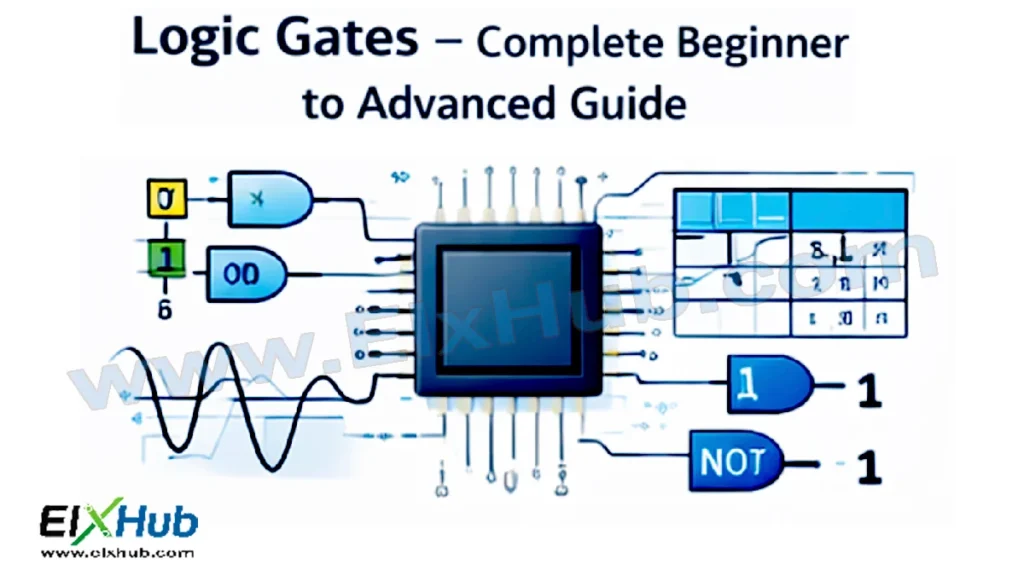
Feature Image
Description: Digital electronics concept illustration showing binary numbers, logic gates, and ICs in brand color #2599DD. Size: 768×432.
Suggested Filenamedigital_electronics_feature_image.png
Alt Text
Digital electronics basics showing binary numbers, logic gates, and digital ICs.
SEO Title
Logic Gates Explained – Complete Beginner to Advanced Digital Electronics Guide
Meta Description
Learn logic gates from basics to advanced. Understand AND, OR, NOT, NAND, NOR, XOR gates, truth tables, ICs, and real applications.