
Introduction
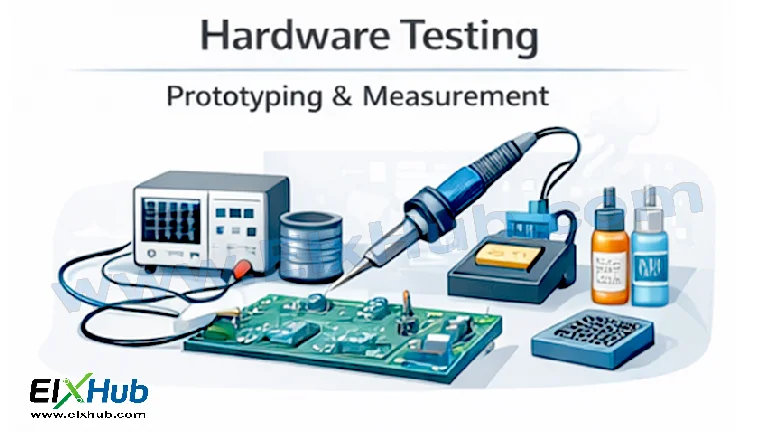
Hardware testing, prototyping, and measurement form the backbone of practical electronics. No matter how good a circuit looks on paper or in simulation, real-world performance can only be verified through proper testing and measurement. For beginners, hardware testing helps bridge the gap between theory and practice, while for professionals, it ensures reliability, safety, and performance compliance.
In electronics, prototyping allows engineers and hobbyists to quickly build and modify circuits before final production. Measurement tools then help observe voltages, currents, signals, and timing behavior to confirm whether the circuit is operating as intended. Together, prototyping and measurement are essential for debugging, optimization, and validation of electronic systems.
This article explains hardware testing in a beginner-friendly yet detailed manner, covering prototyping methods, commonly used measurement instruments, testing techniques, best practices, and real-world applications.
What is Hardware Testing in Electronics
Hardware testing refers to the process of verifying the physical behavior of an electronic circuit or system using real components and instruments. Unlike software testing, hardware testing deals with electrical parameters such as voltage, current, resistance, frequency, noise, and power dissipation.
The main objectives of hardware testing include:
Ensuring correct circuit operation
Detecting faults or wiring errors
Validating component performance
Measuring real-world electrical characteristics
Improving reliability and safety
Hardware testing is performed at different stages, from early prototyping to final product validation.
Prototyping in Electronics
Prototyping is the process of building a preliminary version of a circuit to test its functionality. It allows rapid experimentation without committing to a final PCB design.
Why Prototyping is Important
Prototyping helps identify design flaws early, reduces development cost, and shortens design cycles. It also provides hands-on understanding of circuit behavior, which is especially important for learners.
Key benefits include:
Easy modification and experimentation
Faster debugging
Low-cost development
Real-world performance evaluation
Common Prototyping Methods
Different prototyping methods are used depending on complexity, frequency, and power level of the circuit.
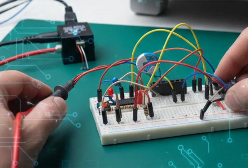
Breadboard Prototyping
Breadboards are the most popular prototyping tools for beginners and low-frequency circuits.
Advantages:
No soldering required
Reusable
Fast circuit changes
Limitations:
Not suitable for high-frequency or high-current circuits
Loose connections may cause noise
Perfboard and Stripboard
Perfboards and stripboards are semi-permanent prototyping solutions.
Advantages:
More stable than breadboards
Suitable for medium-complexity circuits
Limitations:
Requires soldering
Circuit changes are harder
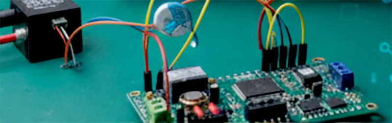
Prototype PCB
Prototype PCBs are custom-made boards used when the circuit design is almost finalized.
Advantages:
Realistic layout
Better signal integrity
Limitations:
Higher cost
Less flexible for changes
Measurement in Electronics
Measurement is the process of quantifying electrical parameters using instruments. Accurate measurement is critical for understanding circuit behavior and diagnosing faults.
Key Electrical Quantities Measured
Voltage
Current
Resistance
Capacitance
Inductance
Frequency
Waveform shape
Power
Essential Hardware Testing Instruments
Several instruments are commonly used in electronics labs and workshops.
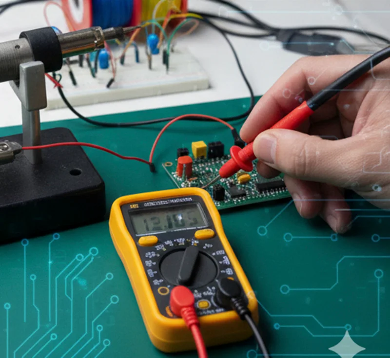
Digital Multimeter (DMM)
A multimeter is the most essential tool for electronics testing.
Functions:
Voltage measurement (AC and DC)
Current measurement
Resistance measurement
Continuity testing
Diode testing
Oscilloscope
An oscilloscope is used to visualize electrical signals over time.
Key uses:
Observing waveforms
Measuring frequency and period
Analyzing signal noise and distortion
Debugging timing issues

Power Supply
A regulated bench power supply provides controlled voltage and current to a circuit.
Benefits:
Adjustable voltage and current
Current limiting for safety
Stable output

Function Generator
A function generator produces test signals such as sine, square, and triangle waves.
Applications:
Testing amplifiers
Frequency response analysis
Signal injection
Logic Analyzer
Logic analyzers are used in digital electronics to analyze multiple digital signals simultaneously.
Applications:
Debugging microcontroller interfaces
Analyzing timing relationships
Testing communication protocols
Prototyping and Measurement Workflow
A typical hardware testing workflow follows a structured approach.
Step 1: Build the prototype
Step 2: Perform visual inspection
Step 3: Power-up testing with current limiting
Step 4: Measure key voltages and currents
Step 5: Observe signals using oscilloscope
Step 6: Debug and modify circuit
Step 7: Validate performance
Testing Techniques in Electronics
Different testing techniques are used depending on the goal.
Continuity Testing
Used to verify proper connections and detect broken wires or solder joints.
Voltage Testing
Ensures correct voltage levels at various nodes.
Signal Testing
Checks waveform shape, amplitude, and frequency.
Load Testing
Verifies circuit behavior under real operating conditions.
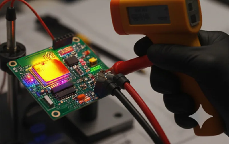
Thermal Testing
Ensures components operate within safe temperature limits.
Safety Practices in Hardware Testing
Safety is critical when working with electronic hardware.
Important safety rules:
Always power off before modifying circuits
Use current-limited power supplies
Avoid short circuits
Discharge capacitors before handling
Use insulated probes
Wear eye protection when necessary
Common Hardware Testing Mistakes
Beginners often make mistakes that lead to confusion or component damage.
Common mistakes include:
Incorrect wiring
Wrong component values
Exceeding voltage or current ratings
Poor grounding
Improper probe connections
Understanding and avoiding these mistakes improves testing accuracy and safety.
Hardware Testing for Beginners
For beginners, hardware testing builds confidence and practical skills.
Recommended starter tools:
Basic multimeter
Breadboard
Low-voltage power supply
Basic components
Simple projects such as LED circuits, voltage dividers, and timers are ideal for learning testing techniques.
Hardware Testing in Professional Electronics
In professional environments, hardware testing ensures compliance with standards and long-term reliability.
Applications include:
Consumer electronics testing
Industrial control systems
Automotive electronics
Medical devices
Aerospace systems
Advanced testing may involve automated test equipment, environmental chambers, and compliance testing.
Advantages of Proper Hardware Testing
Improves product reliability
Reduces failure rates
Enhances safety
Optimizes performance
Saves development cost
Limitations of Hardware Testing
Time-consuming for complex systems
Requires specialized equipment
Measurement errors due to probe loading
Environmental factors may affect results
Despite these limitations, hardware testing remains essential.
Conclusion
Hardware testing, prototyping, and measurement are indispensable skills in electronics. They allow engineers and learners to transform theoretical designs into functional, reliable systems. By understanding prototyping methods, mastering measurement tools, and following safe testing practices, anyone can effectively test and debug electronic circuits. Whether you are a beginner building your first breadboard project or a professional validating a complex system, proper hardware testing ensures accuracy, safety, and confidence in your designs.
SEO Title
Hardware Testing, Prototyping and Measurement Explained for Beginners
Focus Keyword
Hardware Testing and Measurement
Meta Description
Learn hardware testing, prototyping, and measurement techniques in electronics including breadboards, multimeters, oscilloscopes, and best testing practices for beginners.


