
Introduction
In basic electronics, understanding series and parallel circuits is one of the most important foundational skills for beginners. Almost every electronic or electrical system you encounter—whether it is a household wiring setup, a mobile phone circuit board, or an industrial control panel—is built using a combination of series and parallel connections.
Series and parallel circuits define how components are connected and how current and voltage behave within a circuit. These concepts explain why some bulbs glow dimmer, why others stay bright, why devices continue working even if one part fails, and how engineers design safe and efficient electrical systems.
This complete beginner guide explains series and parallel circuits in simple language, covering definitions, working principles, current and voltage behavior, advantages, disadvantages, real-world applications, and common mistakes. By the end of this article, you will clearly understand how series and parallel circuits work and how to identify them in real life.
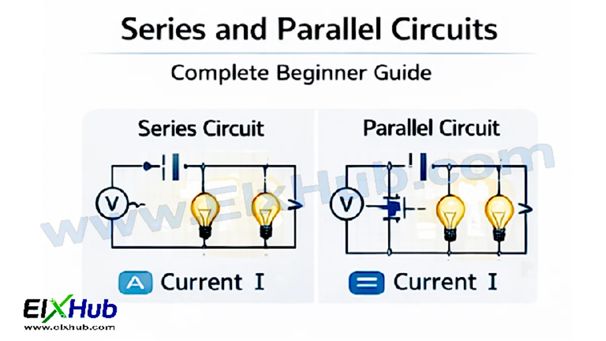
[Image Placeholder: Simple series and parallel circuit comparison diagram]
What Is an Electrical Circuit?
An electrical circuit is a closed path that allows electric current to flow from a power source, through components, and back to the source.
Every basic circuit consists of:
- A power source (battery or supply)
- Conducting path (wires)
- Load (bulb, resistor, motor)
- Control element (switch)
The way these components are connected determines whether the circuit is series, parallel, or a combination of both.
[Image Placeholder: Basic electrical circuit with battery, switch, and bulb]
What Is a Series Circuit?
A series circuit is a circuit in which components are connected one after another in a single path. The same current flows through every component because there is only one path for the current to follow.
If any component in a series circuit fails or is disconnected, the entire circuit stops working.
Key Characteristics of Series Circuits
| Feature | Description |
|---|---|
| Current | Same through all components |
| Voltage | Divided among components |
| Path | Single path |
| Failure effect | Entire circuit stops |
[Image Placeholder: Series circuit with multiple bulbs in a single path]
How Current Works in a Series Circuit
In a series circuit:
- The current is the same everywhere
- Current leaving the power source flows through each component in sequence
This means that adding more components increases the total resistance, which reduces the current flowing in the circuit.
Example
If three resistors are connected in series, the same current flows through all three, regardless of their resistance values.
[Image Placeholder: Current flow arrows in a series circuit]
How Voltage Works in a Series Circuit
In a series circuit:
- The total voltage is divided among the components
- Each component receives a portion of the source voltage
The voltage drop across each component depends on its resistance.
Voltage Rule for Series Circuits
Total voltage = Sum of individual voltage drops
[Image Placeholder: Voltage division across resistors in series]
Resistance in a Series Circuit
The total resistance in a series circuit is the sum of all individual resistances.
| Formula | Explanation |
|---|---|
| Rₜ = R₁ + R₂ + R₃ | Total resistance |
As resistance increases, current decreases, according to Ohm’s Law.
[Image Placeholder: Series resistors with total resistance label]
Advantages of Series Circuits
Series circuits offer several benefits:
- Simple design
- Easy to analyze
- Requires fewer wires
- Used in current-limiting applications
Because of their simplicity, series circuits are often used in basic learning experiments.
Disadvantages of Series Circuits
Despite their simplicity, series circuits have limitations:
- One failure breaks the entire circuit
- Voltage is shared, reducing power to each load
- Not suitable for household wiring
[Image Placeholder: Series bulbs where one broken bulb turns all off]
Common Applications of Series Circuits
| Application | Reason |
|---|---|
| Decorative string lights | Simple wiring |
| Fuse connections | Overcurrent protection |
| Sensors | Same current measurement |
| LED current limiting | Controlled current |
Series circuits are rarely used alone in modern power systems but are important building blocks.
What Is a Parallel Circuit?
A parallel circuit is a circuit where components are connected across the same voltage source, creating multiple paths for current to flow.
Each component operates independently, and failure of one does not affect others.
Key Characteristics of Parallel Circuits
| Feature | Description |
|---|---|
| Current | Divided among branches |
| Voltage | Same across all components |
| Path | Multiple paths |
| Failure effect | Other branches continue |
[Image Placeholder: Parallel circuit with multiple branches]
How Current Works in a Parallel Circuit
In a parallel circuit:
- The total current splits among the branches
- Each branch carries current based on its resistance
Lower resistance branches draw more current.
Current Rule for Parallel Circuits
Total current = Sum of branch currents
[Image Placeholder: Current splitting in parallel branches]
How Voltage Works in a Parallel Circuit
In a parallel circuit:
- The voltage across each branch is the same
- Each component receives full source voltage
This is why household appliances operate at the same voltage.
[Image Placeholder: Equal voltage across parallel loads]
Resistance in a Parallel Circuit
The total resistance of a parallel circuit is less than the smallest branch resistance.
| Formula | Explanation |
|---|---|
| 1/Rₜ = 1/R₁ + 1/R₂ + 1/R₃ | Parallel resistance |
Adding more branches decreases total resistance and increases current.
[Image Placeholder: Parallel resistors with equivalent resistance]
Advantages of Parallel Circuits
Parallel circuits offer many benefits:
- Each device gets full voltage
- Failure of one device does not affect others
- Ideal for power distribution
- Easy expansion
Disadvantages of Parallel Circuits
Parallel circuits also have drawbacks:
- More complex wiring
- Higher current demand
- Increased cost
- Requires proper protection
[Image Placeholder: Complex parallel wiring diagram]
Series vs Parallel Circuits: Comparison Table
| Parameter | Series Circuit | Parallel Circuit |
|---|---|---|
| Current | Same everywhere | Divided |
| Voltage | Divided | Same |
| Paths | One | Multiple |
| Reliability | Low | High |
| Wiring | Simple | Complex |
| Usage | Limited | Common |
This comparison highlights why parallel circuits dominate real-world applications.
Combination (Series-Parallel) Circuits
Most real circuits are combination circuits, using both series and parallel connections.
Examples include:
- Electronic devices
- Power supplies
- Industrial panels
Understanding series and parallel basics makes combination circuits easier to analyze.
[Image Placeholder: Combination series-parallel circuit diagram]
Series and Parallel Circuits in Real Life
Household Wiring
Homes use parallel wiring so:
- Appliances receive full voltage
- Devices operate independently
- Safety and reliability are improved
Electronic Devices
Circuit boards combine series and parallel components to:
- Control current
- Divide voltage
- Protect components
[Image Placeholder: Household parallel wiring illustration]
Series and Parallel Circuits with Bulbs
| Setup | Brightness | Reason |
|---|---|---|
| Series bulbs | Dimmer | Voltage divided |
| Parallel bulbs | Brighter | Full voltage |
This simple bulb example is commonly used to demonstrate circuit behavior.
[Image Placeholder: Bulbs in series vs parallel]
Series and Parallel Circuits with Batteries
Batteries can also be connected in series or parallel.
| Connection | Effect |
|---|---|
| Series batteries | Increases voltage |
| Parallel batteries | Increases current capacity |
This concept is widely used in power banks and battery packs.
[Image Placeholder: Batteries in series and parallel]
Common Beginner Mistakes
Beginners often:
- Confuse current flow directions
- Assume voltage is same in series
- Ignore resistance effects
- Misidentify circuit type
Careful observation and practice help avoid these mistakes.
Safety Considerations
- Avoid short circuits
- Use proper insulation
- Do not overload parallel branches
- Always disconnect power before changes
[Image Placeholder: Electrical safety symbols]
Why Series and Parallel Circuits Matter
Understanding series and parallel circuits is essential for:
- Learning electronics
- Troubleshooting faults
- Designing circuits
- Understanding power systems
These concepts form the foundation for advanced topics like analog electronics, digital electronics, and power electronics.
Conclusion
Series and parallel circuits are the backbone of all electrical and electronic systems. A series circuit provides simplicity and controlled current, while a parallel circuit offers reliability, full voltage delivery, and independent operation of components. In real-world applications, a combination of both is used to achieve efficiency, safety, and performance.
For beginners in basic electronics, mastering series and parallel circuits builds confidence and prepares you for more advanced concepts such as Ohm’s Law applications, circuit analysis, amplifiers, and power electronics systems. With practice and observation, these concepts become intuitive and practical.
Image Reference Table (For Future Use)
| Image Filename | Suggested Alt Text | Description |
|---|---|---|
| series-parallel-overview.png | Series vs parallel overview | Basic comparison |
| basic-circuit.png | Basic electrical circuit | Power source and load |
| series-circuit.png | Series circuit | Single path |
| series-current.png | Series current flow | Same current |
| series-voltage.png | Series voltage division | Voltage drops |
| parallel-circuit.png | Parallel circuit | Multiple paths |
| parallel-current.png | Parallel current flow | Current division |
| parallel-voltage.png | Parallel voltage | Same voltage |
| combination-circuit.png | Series-parallel circuit | Mixed connections |
| household-wiring.png | Parallel home wiring | Real-life example |
SEO Title: Series and Parallel Circuits Explained – Complete Beginner Guide
Meta Description: Learn series and parallel circuits explained simply for beginners. Understand current, voltage, resistance, advantages, applications, and real-life examples.


