Introduction
Switched Mode Power Supplies (SMPS) are one of the most important and widely used power electronic systems in modern industry and consumer electronics. From industrial automation panels and telecommunications equipment to computers, chargers, and renewable energy systems, SMPS play a critical role in converting and regulating electrical power efficiently. Unlike linear power supplies, which dissipate excess power as heat, SMPS use high-frequency switching techniques to achieve high efficiency, compact size, and excellent performance.
In the field of Power Electronics, SMPS represent a perfect combination of semiconductor switching devices, control circuits, magnetic components, and feedback mechanisms. Their ability to handle wide input voltage ranges, provide electrical isolation, and deliver regulated output makes them indispensable in industrial and commercial applications. This article explains the working principle, design considerations, major topologies, advantages, limitations, and applications of SMPS in a detailed and structured manner.
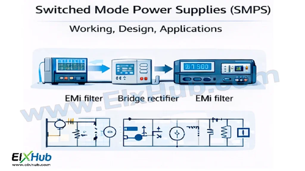
[Image Placeholder: Overview of SMPS used in industrial and electronic systems]
What is a Switched Mode Power Supply?
A Switched Mode Power Supply is an electronic power conversion system that converts electrical power from one form to another using high-frequency switching devices such as MOSFETs or IGBTs. The switching action allows the power supply to operate at much higher frequencies compared to traditional linear regulators, significantly reducing size and losses.
Key characteristics of SMPS include:
- High efficiency
- Compact and lightweight construction
- Wide input voltage operation
- Ability to provide multiple output voltages
- Electrical isolation when required
Basic Working Principle of SMPS
The operation of an SMPS can be broadly divided into the following stages:
- Input AC or DC power
- Rectification and filtering
- High-frequency switching
- Energy transfer through inductors or transformers
- Output rectification and filtering
- Feedback and control
[Image Placeholder: Basic SMPS block diagram]
Step-by-Step Working
| Stage | Description |
|---|---|
| Input Stage | AC mains or DC source is supplied to the SMPS |
| Rectifier | AC is converted into unregulated DC using diodes |
| DC Filter | Capacitors smooth the rectified DC |
| Switching Stage | Power semiconductor switches operate at high frequency |
| Transformer/Inductor | Transfers energy and provides voltage scaling or isolation |
| Output Rectifier | High-frequency AC is converted back to DC |
| Output Filter | DC output is smoothed and regulated |
| Feedback Control | Output voltage is sensed and regulated |
The switching device operates in either fully ON or fully OFF state, minimizing power loss and improving efficiency.
Why SMPS Are More Efficient Than Linear Power Supplies
Linear power supplies regulate voltage by dissipating excess energy as heat, which results in poor efficiency especially at high power levels. In contrast, SMPS regulate voltage by controlling the duty cycle of switching devices.
| Parameter | Linear Power Supply | SMPS |
|---|---|---|
| Efficiency | Low | High |
| Size | Large | Compact |
| Heat Dissipation | High | Low |
| Input Voltage Range | Narrow | Wide |
| Weight | Heavy | Lightweight |
[Image Placeholder: Comparison between linear supply and SMPS size]
Main Components of an SMPS
An SMPS consists of several critical components, each serving a specific function.
Power Switching Devices
- MOSFETs for low to medium power
- IGBTs for higher power applications
These devices switch at high frequencies, typically from tens of kHz to several MHz.
Magnetic Components
- Transformers for isolation and voltage scaling
- Inductors for energy storage and filtering
Control ICs
Control integrated circuits regulate the switching frequency, duty cycle, and protection mechanisms such as overcurrent and overvoltage protection.
Feedback Network
Feedback ensures output voltage regulation by adjusting the switching operation based on load conditions.
[Image Placeholder: Internal components of an SMPS]
SMPS Topologies
Different SMPS topologies are used depending on power level, isolation requirements, and application.
Non-Isolated SMPS Topologies
These topologies do not provide galvanic isolation between input and output.
| Topology | Key Features | Typical Applications |
|---|---|---|
| Buck Converter | Step-down voltage | DC regulators |
| Boost Converter | Step-up voltage | Battery-powered systems |
| Buck-Boost Converter | Step-up or step-down | Portable devices |
| Cuk Converter | Low ripple output | Precision electronics |
[Image Placeholder: Buck and Boost converter circuits]
Isolated SMPS Topologies
These topologies use transformers to provide electrical isolation.
| Topology | Power Range | Applications |
|---|---|---|
| Flyback | Low power | Chargers, adapters |
| Forward | Medium power | Industrial control |
| Push-Pull | Medium power | Inverters |
| Half-Bridge | Medium to high power | SMPS, UPS |
| Full-Bridge | High power | Industrial power supplies |
[Image Placeholder: Flyback and forward converter diagrams]
Design Considerations of SMPS
Designing an SMPS requires careful consideration of electrical, thermal, and safety aspects.
Input and Output Requirements
- Input voltage range
- Output voltage and current
- Power rating
Switching Frequency Selection
Higher switching frequency reduces transformer size but increases switching losses and EMI.
Efficiency and Thermal Management
- Heat sinks and PCB thermal design
- Proper selection of power devices
- Use of high-efficiency topologies
EMI and Noise Reduction
- Input and output filters
- Proper PCB layout
- Shielding and grounding techniques
[Image Placeholder: SMPS PCB layout with EMI filters]
Protection Features
Common protection mechanisms include:
- Overcurrent protection
- Overvoltage protection
- Short-circuit protection
- Thermal shutdown
Applications of SMPS in Power Electronics
SMPS are used across a wide range of power electronics applications.
Industrial Applications
- PLC power supplies
- Motor drive control circuits
- CNC machines
- Industrial automation panels
Consumer Electronics
- Computers and laptops
- Mobile chargers
- Televisions and audio systems
Renewable Energy Systems
- Solar inverters
- Battery chargers
- Energy storage systems
Telecommunications
- Base stations
- Networking equipment
- Data centers
[Image Placeholder: SMPS applications in industrial and consumer electronics]
Advantages of SMPS
SMPS offer several advantages over conventional power supplies:
- High efficiency
- Reduced size and weight
- Wide operating voltage range
- Better voltage regulation
- Low heat generation
- High power density
These advantages make SMPS the preferred choice in modern power electronic systems.
Limitations and Challenges of SMPS
Despite their advantages, SMPS also present certain challenges:
- Complex circuit design
- High-frequency noise and EMI
- More difficult troubleshooting
- Cost of high-quality components
Proper design and filtering techniques are essential to overcome these limitations.
Future Trends in SMPS Technology
With the advancement of power electronics, SMPS technology continues to evolve:
- Use of wide bandgap devices such as SiC and GaN
- Higher switching frequencies
- Improved digital control techniques
- Higher efficiency and power density
- Integration with smart control and IoT systems
[Image Placeholder: Next-generation SMPS using wide bandgap devices]
Conclusion
Switched Mode Power Supplies are a cornerstone of modern power electronics, offering efficient, compact, and reliable power conversion solutions. Their working principle based on high-frequency switching enables superior performance compared to traditional linear power supplies. With various topologies available, SMPS can be tailored to meet the needs of industrial, commercial, and consumer applications.
Understanding the working, design considerations, and applications of SMPS is essential for engineers, students, and professionals working in the field of power electronics. As technology advances, SMPS will continue to play a vital role in energy-efficient and high-performance electronic systems.
Image Reference Table
| Image Filename | Description | Alt Text |
|---|---|---|
| smps-overview.png | Overview of SMPS systems | Switched Mode Power Supply overview |
| smps-block-diagram.png | Basic SMPS block diagram | SMPS working diagram |
| linear-vs-smps.png | Size comparison between linear supply and SMPS | Linear vs SMPS comparison |
| smps-components.png | Internal components of SMPS | SMPS internal components |
| buck-boost.png | Buck and Boost converter circuits | Buck and Boost converters |
| isolated-topologies.png | Isolated SMPS topologies | Flyback and forward converters |
| smps-layout.png | SMPS PCB layout and EMI filters | SMPS PCB and EMI control |
| smps-applications.png | SMPS applications | SMPS industrial applications |
| future-smps.png | Advanced SMPS with modern devices | Next-generation SMPS |
SEO Title
Switched Mode Power Supplies (SMPS) – Working Principle, Design, and Applications
Meta Description
Learn about Switched Mode Power Supplies (SMPS), including working principles, design considerations, topologies, advantages, and applications in power electronics.