Introduction
DC motor control is one of the most important and practical applications of Power Electronics. DC motors are widely used in industries due to their simple construction, high starting torque, wide speed control range, and ease of control. From conveyor belts, electric vehicles, cranes, rolling mills, and robotics to household appliances, DC motors remain highly relevant even in the era of AC drives and brushless motors.
Power electronics enables efficient, precise, and reliable control of DC motors by using semiconductor devices such as SCRs, MOSFETs, and IGBTs. By controlling voltage, current, and switching patterns, power electronic converters allow smooth speed variation, controlled starting, energy-efficient operation, and safe braking. This article provides a deep and practical explanation of DC motor control, focusing on speed control techniques, braking methods, and real-world applications.
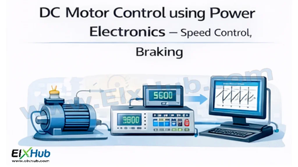
[Image Placeholder: DC motor with power electronic controller overview]
Basics of DC Motors Relevant to Control
Before understanding control techniques, it is essential to review the basic equations governing DC motor operation.
Voltage Equation of DC Motor
The armature voltage equation is:
Va = Eb + IaRa
Where:
- Va = Armature voltage
- Eb = Back EMF
- Ia = Armature current
- Ra = Armature resistance
The back EMF is proportional to speed:
Eb ∝ ΦN
Where:
- Φ = Flux per pole
- N = Speed of motor
This relationship clearly shows that motor speed can be controlled by varying armature voltage or flux, which is the foundation of DC motor control using power electronics.
[Image Placeholder: DC motor equivalent circuit]
Need for Power Electronics in DC Motor Control
Traditional DC motor control methods using rheostats or resistive controllers suffer from high power losses, poor efficiency, and limited control accuracy. Power electronics overcomes these limitations.
Key benefits include:
- High efficiency
- Smooth speed variation
- Compact controller size
- Regenerative braking capability
- Precise torque and speed control
- Reduced maintenance and energy consumption
Classification of DC Motor Control Methods
DC motor control methods using power electronics can be broadly classified as:
| Control Method | Parameter Controlled | Typical Devices Used |
|---|---|---|
| Armature Voltage Control | Speed below base speed | SCRs, MOSFETs, IGBTs |
| Field Control | Speed above base speed | Controlled rectifiers |
| PWM Control | Fine speed regulation | MOSFETs, IGBTs |
| Chopper Control | High efficiency DC drives | MOSFETs, IGBTs |
[Image Placeholder: Classification of DC motor control methods]
Speed Control of DC Motors Using Power Electronics
Armature Voltage Control Method
In this method, motor speed is controlled by varying the armature voltage while keeping the field current constant.
Speed ∝ Armature Voltage
This method is widely used for speeds below rated speed.
Controlled Rectifier-Based Speed Control
Single-phase or three-phase controlled rectifiers using SCRs provide variable DC voltage to the motor.
| Rectifier Type | Power Level | Applications |
|---|---|---|
| Single-phase Half-Controlled | Low power | Small drives |
| Single-phase Full-Controlled | Medium power | Machine tools |
| Three-phase Full-Controlled | High power | Industrial DC drives |
[Image Placeholder: DC motor speed control using SCR rectifier]
Advantages:
- Simple circuit
- Suitable for high power
- Rugged operation
Limitations:
- Poor power factor
- High harmonic distortion
Chopper-Controlled DC Motor Drives
Chopper control is the most efficient and widely used method for DC motor speed control in modern systems.
A DC chopper converts fixed DC input into variable DC output by controlling the duty cycle.
Speed ∝ Duty Cycle
[Image Placeholder: DC motor speed control using DC chopper]
Types of Chopper Control
| Chopper Type | Quadrant Operation | Description |
|---|---|---|
| Type A | First quadrant | Motoring only |
| Type B | Second quadrant | Regenerative braking |
| Type C | First and second | Motoring + braking |
| Type D | First and fourth | Reversal of voltage |
| Type E | Four-quadrant | Full control |
PWM Control Technique
Pulse Width Modulation (PWM) is widely used in DC motor drives for smooth and precise speed control.
Key advantages of PWM:
- Low power loss
- High efficiency
- Smooth torque response
- Reduced current ripple
[Image Placeholder: PWM waveform for DC motor control]
Closed-Loop Speed Control of DC Motors
In industrial applications, open-loop control is often insufficient. Closed-loop control uses feedback to maintain constant speed under varying load conditions.
Components of Closed-Loop DC Drive
| Component | Function |
|---|---|
| Speed Sensor | Measures actual speed |
| Controller | Compares actual and reference speed |
| Power Converter | Adjusts motor voltage |
| DC Motor | Mechanical output |
[Image Placeholder: Closed-loop DC motor speed control system]
Closed-loop control improves:
- Speed accuracy
- Load regulation
- Dynamic response
Braking of DC Motors Using Power Electronics
Braking is as important as speed control, especially in applications requiring fast stopping, safety, or energy recovery.
Types of Braking in DC Motors
| Braking Type | Energy Flow | Description |
|---|---|---|
| Mechanical Braking | Dissipated mechanically | Friction-based |
| Dynamic Braking | Dissipated electrically | Resistor-based |
| Regenerative Braking | Returned to source | Energy efficient |
| Plugging | Reverse torque | Fast but inefficient |
[Image Placeholder: DC motor braking methods]
Dynamic Braking
In dynamic braking, the motor acts as a generator, and the generated energy is dissipated in an external resistor.
Advantages:
- Simple implementation
- Effective stopping
Disadvantages:
- Energy wastage as heat
Regenerative Braking
In regenerative braking, power electronics redirect generated energy back to the supply or battery.
Applications:
- Electric vehicles
- Elevators
- Cranes
[Image Placeholder: Regenerative braking of DC motor]
Benefits:
- Energy saving
- Reduced heating
- Improved system efficiency
Plugging (Reverse Current Braking)
Plugging involves reversing the supply polarity while the motor is running.
Characteristics:
- Very fast braking
- High current and losses
- Used only for short durations
Four-Quadrant Operation of DC Motor Drives
Power electronic controllers enable DC motors to operate in all four quadrants.
| Quadrant | Speed | Torque | Mode |
|---|---|---|---|
| First | Positive | Positive | Forward motoring |
| Second | Positive | Negative | Forward braking |
| Third | Negative | Negative | Reverse motoring |
| Fourth | Negative | Positive | Reverse braking |
[Image Placeholder: Four-quadrant operation of DC motor]
Four-quadrant drives are essential in applications requiring frequent reversal and braking.
Power Semiconductor Devices Used in DC Motor Control
| Device | Power Level | Typical Use |
|---|---|---|
| SCR | High | Industrial drives |
| MOSFET | Low to medium | PWM drives |
| IGBT | Medium to high | EVs, traction |
| Diode | Auxiliary | Freewheeling |
[Image Placeholder: Power devices used in DC motor controllers]
Applications of DC Motor Control Using Power Electronics
DC motor drives are extensively used in:
- Electric vehicles
- Rolling mills
- Elevators and hoists
- Cranes and conveyors
- Robotics and automation
- Printing presses
- Steel and paper industries
[Image Placeholder: Industrial applications of DC motor drives]
Advantages of Power Electronic DC Motor Control
- High efficiency
- Precise speed and torque control
- Smooth starting and braking
- Energy recovery through regeneration
- Compact and reliable systems
Limitations and Challenges
- Brush maintenance in conventional DC motors
- EMI due to high-frequency switching
- Complex control circuits
- Initial system cost
Despite these challenges, DC motor control using power electronics remains highly effective and widely adopted.
Future Trends in DC Motor Control
- Integration with digital controllers and microcontrollers
- Use of AI-based control algorithms
- High-efficiency wide bandgap devices
- Advanced regenerative braking systems
- Smart motor drives with IoT connectivity
[Image Placeholder: Future smart DC motor control systems]
Need to control a motor or a bank of relays? Check out our Ultimate IC Selection Guide to find the right driver chip for your robotics project!
Conclusion
DC motor control using power electronics forms the backbone of many industrial and transportation systems. By employing controlled rectifiers, choppers, PWM techniques, and advanced braking methods, power electronics enables efficient, precise, and flexible control of DC motors. Speed control and braking are no longer limited by mechanical methods, but are now achieved electronically with high accuracy and energy efficiency. Mastering these concepts is essential for anyone working in power electronics, electric drives, and industrial automation.
Image Reference Table
| Image Filename | Description | Alt Text |
|---|---|---|
| dc-motor-overview.png | DC motor and controller overview | DC motor control using power electronics |
| dc-motor-equivalent.png | DC motor equivalent circuit | DC motor equivalent circuit |
| control-methods.png | DC motor control classification | DC motor control methods |
| scr-speed-control.png | SCR-based speed control | DC motor speed control using SCR |
| chopper-control.png | Chopper-controlled DC drive | DC chopper motor control |
| pwm-waveform.png | PWM waveform | PWM control of DC motor |
| closed-loop.png | Closed-loop control system | Closed-loop DC motor control |
| braking-types.png | Braking methods | DC motor braking techniques |
| regenerative-braking.png | Regenerative braking | Regenerative braking of DC motor |
| four-quadrant.png | Four-quadrant operation | Four quadrant DC drive |
| applications.png | Industrial applications | DC motor industrial applications |
| future-control.png | Smart DC motor control | Future DC motor control systems |
SEO Title
DC Motor Control Using Power Electronics – Speed Control and Braking Techniques
Meta Description
Learn DC motor control using power electronics, covering speed control methods, braking techniques, chopper drives, PWM control, and industrial applications.