Introduction
Inverters are one of the most critical building blocks of modern power electronics. An inverter converts direct current (DC) power into alternating current (AC) power with a desired voltage level, frequency, and waveform quality. Almost every modern electrical and electronic system that relies on AC power but is fed from a DC source depends on inverters. Examples include solar power systems, uninterruptible power supplies (UPS), electric vehicles, motor drives, and grid-connected renewable energy systems.
With the increasing adoption of renewable energy and energy-efficient motor control, inverter technology has evolved significantly. Early inverters produced simple square-wave outputs, but modern inverters use advanced Pulse Width Modulation (PWM) techniques to generate near-sinusoidal waveforms with high efficiency and low harmonic distortion.
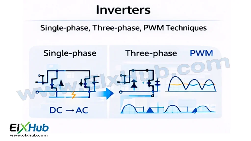
This article provides a complete and in-depth explanation of inverters, covering single-phase and three-phase inverters along with PWM techniques. It explains operating principles, circuit configurations, waveforms, advantages, limitations, and real-world applications. Image placeholders are included for circuit diagrams and waveforms, and an image reference table is provided at the end for easy WordPress integration.
What is an Inverter?
An inverter is a power electronic circuit that converts DC input power into AC output power. The output AC voltage can be controlled in terms of magnitude, frequency, and waveform shape. Semiconductor switching devices such as MOSFETs and IGBTs are commonly used as inverter switches due to their fast switching capability and high efficiency.
[Image Placeholder: Basic inverter block diagram showing DC input and AC output]
Inverters are broadly classified based on:
- Output phase (single-phase or three-phase)
- Output waveform (square wave, quasi-square wave, sinusoidal)
- Switching technique (PWM-based or non-PWM)
Basic Principle of Inverter Operation
The basic principle of inverter operation involves switching the DC input voltage across the load in a controlled manner so that the polarity of the voltage alternates, producing an AC output. This switching action is achieved using power semiconductor devices arranged in specific topologies such as half-bridge or full-bridge configurations.
[Image Placeholder: Polarity reversal concept in inverter operation]
By controlling the switching sequence and timing, the inverter can generate different types of AC waveforms.
Single-Phase Inverters
Overview
Single-phase inverters are used to supply AC power to single-phase loads. They are commonly used in residential solar inverters, small UPS systems, and portable power supplies.
Single-phase inverters are generally classified into:
- Half-bridge inverters
- Full-bridge (H-bridge) inverters
Half-Bridge Single-Phase Inverter
Circuit Configuration
A half-bridge inverter uses two power switches and a split DC supply (or two capacitors connected in series) to generate an AC output.
[Image Placeholder: Half-bridge single-phase inverter circuit diagram]
Working Principle
- When the upper switch is ON, the output voltage is +Vdc/2
- When the lower switch is ON, the output voltage is −Vdc/2
- By alternating the switching of the two devices, an AC waveform is produced
Advantages
- Simple circuit
- Fewer switches
Limitations
- Requires split DC supply
- Lower output voltage utilization
Full-Bridge Single-Phase Inverter
Circuit Configuration
A full-bridge inverter uses four switches arranged in an H-bridge configuration. It does not require a split DC supply and offers better voltage utilization.
[Image Placeholder: Full-bridge single-phase inverter circuit diagram]
Working Principle
- Diagonal switches are turned ON together
- One diagonal pair produces positive output voltage
- The opposite diagonal pair produces negative output voltage
Advantages
- Higher output voltage
- No need for split DC supply
- Better utilization of DC input
Applications
| Application | Reason |
|---|---|
| UPS systems | Reliable AC output |
| Solar inverters | Efficient DC to AC conversion |
| Home power backup | Single-phase AC supply |
Three-Phase Inverters
Overview
Three-phase inverters convert DC power into three-phase AC power. They are widely used in industrial motor drives, electric vehicles, and high-power renewable energy systems. Three-phase power provides smoother torque and higher efficiency compared to single-phase power.
[Image Placeholder: Three-phase inverter block diagram]
Circuit Configuration
A typical three-phase inverter consists of six power switches arranged in three legs, with each leg supplying one phase.
[Image Placeholder: Three-phase inverter circuit diagram]
Working Principle
- Each inverter leg produces a square or PWM voltage waveform
- The phase voltages are displaced by 120 electrical degrees
- The combination results in a rotating magnetic field when applied to a motor
Advantages
- Smooth power delivery
- High efficiency
- Suitable for high-power applications
Applications
| Application | Description |
|---|---|
| Induction motor drives | Speed and torque control |
| Electric vehicles | Traction motor control |
| Industrial automation | Variable speed drives |
| Grid-tied inverters | Three-phase power injection |
Output Waveforms of Inverters
The quality of the inverter output waveform significantly affects performance, efficiency, and harmonic distortion.
[Image Placeholder: Square wave, quasi-square wave, and sinusoidal inverter outputs]
| Waveform Type | Characteristics |
|---|---|
| Square wave | Simple, high harmonics |
| Quasi-square wave | Reduced harmonics |
| Sinusoidal (PWM) | Low distortion, high quality |
Modern inverters primarily use PWM techniques to generate near-sinusoidal waveforms.
Pulse Width Modulation (PWM) Techniques
PWM is the most widely used technique in modern inverters. It controls the width of the switching pulses to shape the output voltage waveform.
[Image Placeholder: Basic PWM concept waveform]
Sinusoidal PWM (SPWM)
In SPWM, a high-frequency triangular carrier signal is compared with a sinusoidal reference signal. The resulting pulses control the inverter switches.
[Image Placeholder: SPWM waveform comparison diagram]
Advantages of SPWM
- Low harmonic distortion
- Adjustable output voltage and frequency
- Better control over motor performance
Space Vector PWM (SVPWM)
SVPWM is an advanced PWM technique used mainly in three-phase inverters. It treats the inverter as a space vector and optimizes switching sequences to maximize DC bus utilization.
[Image Placeholder: Space vector PWM representation]
| Feature | SPWM | SVPWM |
|---|---|---|
| DC bus utilization | Lower | Higher |
| Harmonic performance | Good | Excellent |
| Implementation | Simple | Complex |
Other PWM Techniques
- Hysteresis current control
- Selective harmonic elimination
- Random PWM
Each technique has specific advantages depending on the application.
Harmonics and Filtering
Inverter outputs contain harmonics due to switching action. Harmonics can cause losses, heating, and electromagnetic interference.
[Image Placeholder: Harmonic spectrum of inverter output]
To reduce harmonics, inverters use:
- LC and LCL filters
- Advanced PWM algorithms
- Proper switching frequency selection
Protection and Control in Inverters
Reliable inverter operation requires protection against:
- Overcurrent
- Overvoltage
- Short circuits
- Overtemperature
| Protection Method | Purpose |
|---|---|
| Current sensors | Overcurrent protection |
| Gate drivers with isolation | Safe switching |
| Snubber circuits | dv/dt protection |
| Thermal sensors | Prevent overheating |
[Image Placeholder: Inverter protection circuit overview]
Applications of Inverters
Inverters are used across a wide range of applications:
- Solar photovoltaic systems
- Wind energy conversion systems
- Uninterruptible power supplies
- Electric vehicles
- Industrial motor drives
- HVAC systems
Conclusion
Inverters are a cornerstone of modern power electronics, enabling efficient conversion of DC power into high-quality AC power. Single-phase inverters are ideal for residential and low-power applications, while three-phase inverters dominate industrial and high-power systems. Advanced PWM techniques such as SPWM and SVPWM have significantly improved waveform quality, efficiency, and control flexibility.
A solid understanding of inverter topologies, operating principles, and PWM techniques is essential for designing reliable power electronic systems and for anyone studying or working in power electronics, renewable energy, or motor control.
Image Reference Table
| Filename | Description | Alt Text |
|---|---|---|
| inverter-block.png | Basic inverter block diagram | Inverter block diagram |
| inverter-polarity.png | Polarity reversal principle | Inverter working principle |
| half-bridge-inverter.png | Half-bridge inverter circuit | Half-bridge inverter |
| full-bridge-inverter.png | Full-bridge inverter circuit | Full-bridge inverter |
| three-phase-inverter.png | Three-phase inverter circuit | Three-phase inverter |
| inverter-waveforms.png | Inverter output waveforms | Inverter waveforms |
| pwm-basic.png | PWM principle waveform | PWM technique |
| spwm-waveform.png | Sinusoidal PWM waveform | SPWM inverter |
| svpwm.png | Space vector PWM diagram | SVPWM technique |
| inverter-protection.png | Inverter protection methods | Inverter protection |
SEO Title
Inverters Explained – Single-Phase, Three-Phase, and PWM Techniques in Power Electronics
Meta Description
Learn inverters in power electronics, including single-phase and three-phase inverters, PWM techniques, waveforms, applications, and protection methods for modern AC power systems.