Introduction
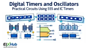
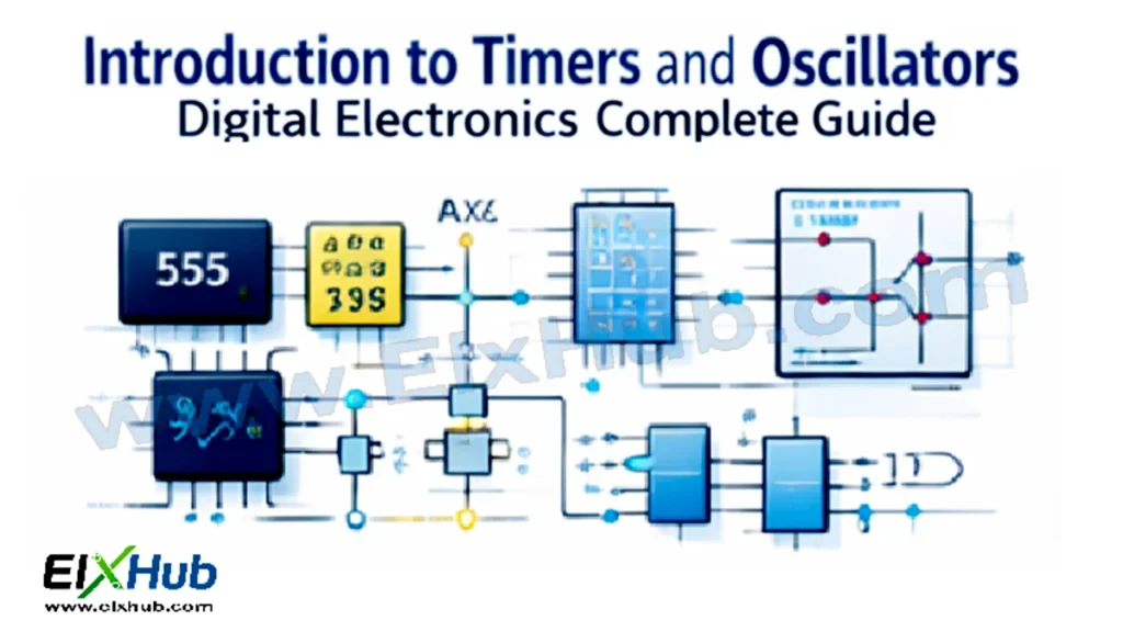
Timers and oscillators are essential components in digital electronics that allow circuits to generate precise time delays and continuous waveforms. Timers are used to measure time intervals, create pulse signals, and manage sequential operations, while oscillators produce repetitive signals such as square waves, sine waves, or clock signals required for synchronizing digital circuits. A thorough understanding of timers and oscillators is crucial for electronics enthusiasts and professionals to design microcontroller projects, signal generators, and communication systems. In this article, we will explore the types, working principles, configurations, and applications of timers and oscillators in digital electronics, along with practical examples and image placeholders ready for WordPress integration.
What is a Timer
A timer is an electronic circuit designed to measure specific time intervals or generate time delays. Timers can be implemented using analog circuits, digital counters, or microcontroller modules. The most commonly used timer IC in electronics is the 555 timer, which can operate in monostable, astable, or bistable modes. Timers are widely used in applications such as delay circuits, pulse width modulation, frequency generation, and sequential switching.
Image Placeholder (Horizontal): 555 timer IC pin diagram and internal block
Types of Timers
Timers can be classified into hardware timers and software timers. Hardware timers use dedicated circuits like the 555 IC, RC networks, or microcontroller internal timers. Software timers are implemented in code using loops or interrupts, providing flexibility but relying on processor timing. In practical electronics, hardware timers are preferred for precise timing and high-frequency applications.
Monostable Timer
Monostable mode, also known as one-shot mode, generates a single output pulse of a specified duration in response to an input trigger. The pulse width is determined by external resistors and capacitors connected to the timer. Monostable timers are commonly used for pulse stretching, switch debouncing, and timer-based control applications.
Image Placeholder (Horizontal): Monostable timer operation diagram
Astable Timer
Astable mode generates continuous square wave pulses without requiring an external trigger. The frequency and duty cycle of the output waveform are controlled by external resistors and capacitors. Astable timers are widely used as clock generators, pulse generators, and oscillators in digital circuits.
Image Placeholder (Horizontal): Astable timer waveform illustration
Bistable Timer
Bistable mode, also called flip-flop mode, allows the timer to maintain one of two stable states. The output changes state when triggered by external inputs. Bistable timers are commonly used in switch toggling, memory storage, and basic flip-flop circuits.
Image Placeholder (Horizontal): Bistable timer logic diagram
Oscillators in Digital Electronics
An oscillator is a circuit that generates a continuous periodic waveform without requiring an external input trigger. Oscillators are fundamental in providing clock signals, timing references, and waveform generation for communication and control systems. Depending on the waveform and design, oscillators can be classified as RC, LC, crystal, or relaxation oscillators.
RC Oscillator
RC oscillators use resistors and capacitors to determine the frequency of oscillation. Common RC oscillator types include phase shift oscillators and Wien bridge oscillators. They are preferred for low-frequency applications and signal generation with moderate stability.
Image Placeholder (Horizontal): RC phase shift oscillator diagram
LC Oscillator
LC oscillators use an inductor (L) and capacitor (C) combination to produce oscillations at a resonant frequency. Types include Colpitts, Hartley, and Clapp oscillators. LC oscillators are ideal for high-frequency applications such as RF signal generation and communication transmitters.
Image Placeholder (Horizontal): LC Colpitts oscillator circuit diagram
Crystal Oscillator
Crystal oscillators use a quartz crystal to maintain highly stable and accurate frequency. They are widely used in microcontroller clock circuits, digital watches, and communication systems where precise timing is critical. The crystal ensures minimal frequency drift over temperature and voltage variations.
Image Placeholder (Horizontal): Crystal oscillator circuit with microcontroller
Relaxation Oscillator
Relaxation oscillators generate non-sinusoidal waveforms such as square or triangular waves using charging and discharging capacitors with nonlinear components like diodes or transistors. They are simple, cost-effective, and suitable for timing and waveform generation in low-frequency applications.
Image Placeholder (Horizontal): Relaxation oscillator waveform illustration
Applications of Timers
Timers are used in countless electronics projects and industrial applications. Monostable timers provide accurate pulse generation for controlling devices. Astable timers serve as clock sources for digital counters, frequency generators, and LED flashers. Bistable timers function as toggle switches, memory elements, and basic logic circuits. Additionally, timers are essential in pulse width modulation for motor speed control, dimming LEDs, and generating precise delays in automation systems.
Image Placeholder (Horizontal): Timer applications in LED flashing and PWM motor control
Applications of Oscillators
Oscillators are the backbone of digital timing and communication systems. RC and LC oscillators generate periodic waveforms for signal processing. Crystal oscillators provide precise clock signals for microcontrollers, computers, and digital watches. Relaxation oscillators are used in low-frequency timers, flashing lights, and audio tone generation. In RF circuits, oscillators serve as local oscillators, carrier wave generators, and modulators. Oscillators are also crucial in waveform generation for function generators and testing instruments.
Image Placeholder (Horizontal): Oscillator applications in microcontroller clock and RF communication
Interfacing Timers and Oscillators with Microcontrollers
Microcontrollers often have built-in timers and can interface with external oscillators for accurate timing. For example, Arduino boards use internal timers for PWM, delays, and interrupts, while external crystal oscillators provide stable clock signals. Understanding how to configure timers, set frequencies, and measure pulse widths is essential for embedded system projects, automated control, and digital signal processing.
Image Placeholder (Horizontal): Microcontroller with internal timer and external crystal oscillator
Common Beginner Mistakes
Many beginners face challenges when working with timers and oscillators. Some common mistakes include incorrect calculation of RC time constants, miswiring external capacitors or resistors, misunderstanding duty cycles, using the wrong oscillator type for the application, and ignoring voltage or frequency limits of ICs. Ensuring proper configuration and testing with a breadboard or simulation software is critical for reliable operation.
FAQs
What is the difference between a timer and an oscillator? A timer generates single or repetitive pulses based on input triggers, while an oscillator generates continuous periodic waveforms without external input.
Can a 555 timer be used as both a timer and oscillator? Yes, depending on the mode—monostable for timer function and astable for oscillator function.
Why are crystal oscillators preferred for microcontroller clocks? Because they provide high frequency stability, low drift, and accurate timing necessary for digital systems.
How can I change the frequency of an astable timer? By adjusting the external resistor and capacitor values connected to the 555 timer IC.
Can timers and oscillators be used in communication systems? Yes, oscillators generate carrier waves, and timers are used in pulse shaping and synchronization.
Related Tutorials on ElxHub
- Basics: Learn more in Integrated Circuits – Basics, Types and Working
- Datasheet: NE555 Precision Timer IC Pinout and Datasheet
- Selection Guide: Compare power options in our Ultimate IC Selection Guide
Conclusion
Timers and oscillators are fundamental in digital electronics for generating precise time delays, periodic waveforms, and clock signals. Understanding monostable, astable, and bistable timers, along with RC, LC, crystal, and relaxation oscillators, enables the design of reliable embedded systems, microcontroller projects, communication circuits, and automation solutions. Mastery of these concepts is essential for anyone aiming to build advanced electronics applications. Proper selection, calculation, and interfacing with microcontrollers or digital circuits ensure accurate timing, stability, and functionality across diverse electronics projects.
Image Placeholders Table (Horizontal images for WordPress insertion):
timer_555_block.png: 555 timer IC pin diagram and internal blockmonostable_timer.png: Monostable timer operation diagramastable_timer.png: Astable timer waveform illustrationbistable_timer.png: Bistable timer logic diagramrc_oscillator.png: RC phase shift oscillator diagramlc_colpitts.png: LC Colpitts oscillator circuit diagramcrystal_oscillator.png: Crystal oscillator circuit with microcontrollerrelaxation_oscillator.png: Relaxation oscillator waveform illustrationtimer_applications.png: Timer applications in LED flashing and PWM motor controloscillator_applications.png: Oscillator applications in microcontroller clock and RF communicationmicrocontroller_timer_oscillator.png: Microcontroller with internal timer and external crystal oscillator