Introduction
Choppers are an essential class of power electronic converters used extensively in DC systems to control and regulate voltage levels efficiently. In power electronics, a chopper is a static DC–DC converter that converts a fixed DC input voltage into a variable DC output voltage. Unlike linear regulators that dissipate excess power as heat, choppers operate on the principle of high-frequency switching, making them highly efficient and suitable for medium- to high-power applications.
With the rapid growth of electric vehicles, renewable energy systems, battery-powered equipment, and DC motor drives, chopper circuits have become increasingly important. They allow precise control of DC voltage and current, enable energy savings, and provide flexibility in system design. From traction systems in electric trains to speed control of DC motors in industrial automation, choppers play a central role in modern DC power conversion.
This article provides a comprehensive explanation of choppers within the main category of Power Electronics. It covers the basic operating principle, classification of choppers, detailed working of different chopper types, control techniques, advantages, limitations, and real-world applications in DC systems. Image placeholders are included for conceptual clarity, and an image reference table is provided at the end for easy content management and SEO optimization.
What is a Chopper in Power Electronics?
A chopper is a power electronic circuit that converts a constant DC input voltage into a controlled DC output voltage by rapidly switching a semiconductor device ON and OFF. The average output voltage is controlled by adjusting the duty cycle of the switching signal.
[Image Placeholder: Basic DC chopper block diagram]
The main components of a DC chopper include:
- DC input source
- Power semiconductor switch (MOSFET, IGBT, or SCR)
- Freewheeling diode
- Load (resistive, inductive, or motor load)
- Control and gate drive circuit
Choppers are sometimes referred to as DC transformers because they perform voltage step-up or step-down functions in DC systems, similar to how transformers operate in AC systems.
Basic Principle of Chopper Operation
The operation of a chopper is based on time ratio control. When the switch is turned ON, the input DC voltage is applied to the load. When the switch is turned OFF, the load is disconnected from the source, and energy stored in the inductive elements may continue to supply current through a freewheeling path.
[Image Placeholder: Chopper ON and OFF states]
The average output voltage is determined by:
- The input voltage
- The switching frequency
- The duty cycle (ratio of ON time to total switching period)
By controlling the duty cycle, the output voltage can be smoothly varied without significant power loss.
Classification of Choppers
Choppers can be classified in several ways based on their operation and application. The most common classification is based on the quadrant of operation in the voltage-current (V–I) plane.
Quadrant-Based Classification
| Chopper Type | Quadrant of Operation | Power Flow |
|---|---|---|
| Class A | First quadrant | Source to load |
| Class B | Second quadrant | Load to source |
| Class C | First and second | Bidirectional current |
| Class D | First and fourth | Bidirectional voltage |
| Class E | All four quadrants | Fully reversible |
Each type serves a specific purpose in DC systems, especially in motor control applications.
Class A Chopper (Step-Down Chopper)
Description
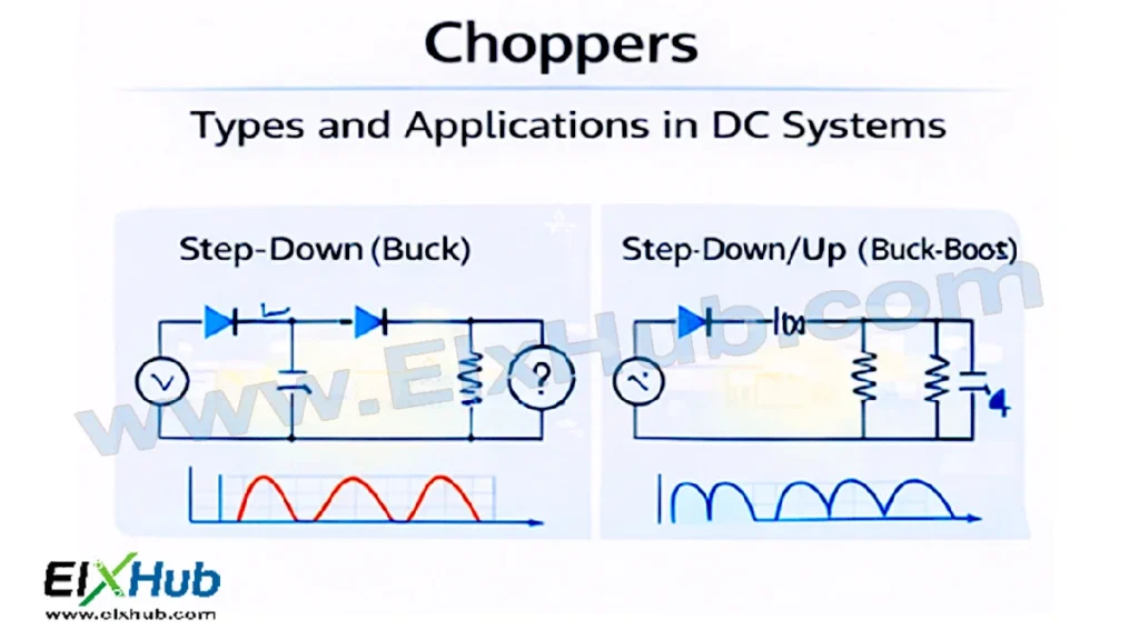
A Class A chopper operates in the first quadrant, where both output voltage and current are positive. It is also known as a step-down chopper because the average output voltage is always less than the input voltage.
[Image Placeholder: Class A chopper circuit diagram]
Working Principle
- When the switch is ON, the input voltage is applied to the load
- When the switch is OFF, the load current continues through the freewheeling diode
- The output voltage is controlled by varying the duty cycle
Applications
| Application | Description |
|---|---|
| DC motor speed control | Forward motoring |
| Battery-powered systems | Voltage regulation |
| DC power supplies | Output voltage control |
Class B Chopper (Step-Up Chopper)
Description
A Class B chopper operates in the second quadrant. The output voltage is positive, but the current flows in the opposite direction. This type of chopper is also known as a step-up or regenerative chopper.
[Image Placeholder: Class B chopper circuit diagram]
Working Principle
- Energy is stored in the inductive load during the ON period
- During the OFF period, the stored energy is returned to the source
- Enables regenerative braking in motor drives
Applications
- Regenerative braking of DC motors
- Energy recovery systems
- Battery charging applications
Class C Chopper (Two-Quadrant Chopper)
Description
A Class C chopper combines Class A and Class B choppers. It operates in both the first and second quadrants, allowing bidirectional current flow while maintaining unidirectional voltage.
[Image Placeholder: Class C chopper circuit diagram]
Key Features
- Suitable for reversible DC motor drives
- Allows motoring and regenerative braking
- Requires two controlled switches
Applications
| Application | Benefit |
|---|---|
| DC motor drives | Forward motoring and braking |
| Electric vehicles | Energy-efficient control |
| Industrial automation | Improved dynamic response |
Class D Chopper (Two-Quadrant Voltage Chopper)
Description
A Class D chopper operates in the first and fourth quadrants, allowing bidirectional voltage but unidirectional current. It is mainly used in applications requiring voltage reversal.
[Image Placeholder: Class D chopper circuit diagram]
Applications
- DC motor reversal
- Bidirectional DC voltage control
Class E Chopper (Four-Quadrant Chopper)
Description
A Class E chopper is a fully controlled chopper that operates in all four quadrants of the V–I plane. It provides complete control over voltage and current direction.
[Image Placeholder: Class E chopper circuit diagram]
Advantages
- Full motoring and braking control
- High flexibility
- Suitable for advanced drive systems
Applications
| Application | Description |
|---|---|
| Electric traction | Complete speed and torque control |
| Robotics | Precise motion control |
| High-performance drives | Four-quadrant operation |
Control Techniques Used in Choppers
Chopper output voltage is controlled using different switching strategies.
Time Ratio Control (TRC)
- Constant frequency control
- Variable duty cycle
- Widely used in modern choppers
[Image Placeholder: Time ratio control waveform]
Current Limit Control
- Maintains current within safe limits
- Protects load and semiconductor devices
Choppers with Inductive Loads
Most practical chopper applications involve inductive loads such as DC motors. Inductance causes current to continue flowing even when the switch is turned OFF.
[Image Placeholder: Chopper with inductive load and freewheeling diode]
The freewheeling diode provides a path for this current, preventing voltage spikes and protecting the switching device.
Advantages of Choppers
Choppers offer several advantages over traditional DC control methods:
- High efficiency
- Compact size
- Fast dynamic response
- Smooth and continuous control
- Reduced power loss
Limitations of Choppers
Despite their advantages, choppers also have some limitations:
- Switching noise and EMI
- Requirement of filtering circuits
- Complex control and protection circuitry
Applications of Choppers in DC Systems
Choppers are widely used in various DC applications, including:
- DC motor speed control
- Electric vehicles
- Battery charging systems
- Renewable energy systems
- Switched-mode DC power supplies
- Traction and transportation systems
[Image Placeholder: Chopper applications in DC motor drive]
Comparison of Choppers with Linear DC Controllers
| Feature | Chopper | Linear Controller |
|---|---|---|
| Efficiency | High | Low |
| Power loss | Low | High |
| Size | Compact | Bulky |
| Control | Flexible | Limited |
Conclusion
Choppers are a fundamental component of DC power conversion in power electronics. By using high-speed switching and duty cycle control, they provide an efficient and flexible method of regulating DC voltage and current. Different types of choppers, ranging from single-quadrant to four-quadrant operation, enable precise control in a wide variety of DC systems, particularly in motor drives and energy conversion applications.
A thorough understanding of chopper types, operating principles, and applications is essential for students, engineers, and professionals working in power electronics, electric drives, and renewable energy systems. As DC-based technologies continue to grow, choppers will remain a key technology shaping the future of efficient power control.
Image Reference Table
| Filename | Description | Alt Text |
|---|---|---|
| chopper-block.png | Basic DC chopper block diagram | DC chopper block diagram |
| chopper-operation.png | Chopper ON and OFF states | Chopper working principle |
| class-a-chopper.png | Class A chopper circuit | Step-down chopper |
| class-b-chopper.png | Class B chopper circuit | Step-up chopper |
| class-c-chopper.png | Class C chopper circuit | Two-quadrant chopper |
| class-d-chopper.png | Class D chopper circuit | Voltage reversal chopper |
| class-e-chopper.png | Class E chopper circuit | Four-quadrant chopper |
| chopper-trc.png | Time ratio control waveform | Chopper control technique |
| chopper-inductive.png | Chopper with inductive load | Chopper with freewheeling diode |
| chopper-applications.png | Applications of choppers | Chopper applications |
SEO Title
Choppers in Power Electronics – Types, Working Principles, and DC Applications
Meta Description
Learn about choppers in power electronics, including types, operating principles, control methods, advantages, and applications in modern DC systems and motor drives.