Introduction
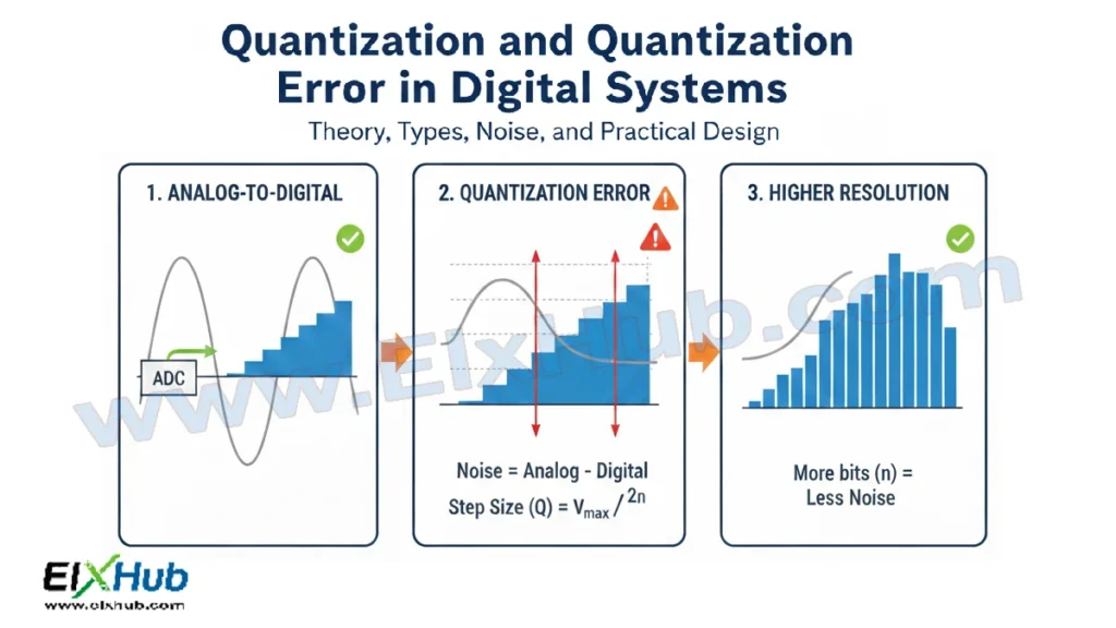
Quantization is a fundamental process in digital electronics that directly follows signal sampling during analog-to-digital conversion. While sampling converts a continuous-time signal into discrete-time samples, quantization converts the continuous amplitude of each sample into a finite set of discrete levels. This process makes it possible for digital systems to store, process, and transmit analog information using binary data.
However, quantization is inherently an approximation process. Because an infinite range of analog values must be represented using a limited number of digital levels, some information loss is unavoidable. This loss manifests as quantization error or quantization noise. Understanding quantization and its effects is essential for designing accurate digital systems such as audio processors, communication systems, data acquisition systems, and embedded electronics.
This article provides a deep and practical explanation of quantization, quantization error, types of quantizers, signal-to-quantization-noise ratio, and real-world implications in digital electronics.
What is Quantization?
Quantization is the process of mapping a continuous range of amplitude values into a finite set of discrete levels. Each sampled value of an analog signal is approximated to the nearest available digital level.
In simple terms, quantization answers the question:
“How accurately can a digital system represent the amplitude of an analog signal?”
The precision of this representation depends on the number of quantization levels, which is determined by the resolution of the ADC.
Quantization Levels and Resolution
The number of quantization levels depends on the number of bits used in the digital representation.
Number of quantization levels = 2ⁿ
Where n is the number of bits.
For example:
An 8-bit ADC has 256 levels
A 10-bit ADC has 1024 levels
A 12-bit ADC has 4096 levels
Higher resolution means smaller step size and more accurate signal representation.
Quantization Step Size
The quantization step size represents the voltage difference between two adjacent quantization levels.
Step size formula
Δ = (Vmax − Vmin) / 2ⁿ
Where:
Δ is the step size
Vmax is maximum input voltage
Vmin is minimum input voltage
Smaller step size results in lower quantization error.
Quantization Process Explained
The quantization process follows these steps:
An analog signal is sampled
Each sample amplitude is compared to reference levels
The sample is assigned to the nearest quantization level
The level is encoded into binary form
Once quantized, the signal is no longer continuous in amplitude.
Types of Quantization
Quantization can be classified based on how amplitude levels are distributed.
Uniform Quantization
In uniform quantization, all quantization levels are equally spaced.
Characteristics:
Simple to implement
Used in most ADCs
Constant step size
Uniform quantization works well when signal amplitudes are evenly distributed.
Non-Uniform Quantization
In non-uniform quantization, step sizes vary across the amplitude range.
Characteristics:
Smaller steps for low amplitudes
Larger steps for high amplitudes
Improved performance for speech and audio
Non-uniform quantization is often implemented using companding techniques such as μ-law and A-law.
Mid-Rise and Mid-Tread Quantizers
Quantizers are also classified based on how zero input is handled.
Mid-rise quantizer:
No zero output level
Step transition at zero
Mid-tread quantizer:
Has a zero output level
Better noise performance for small signals
What is Quantization Error?
Quantization error is the difference between the actual analog value and the quantized digital value.
Quantization error = Actual signal value − Quantized value
This error occurs because the input signal is rounded to the nearest quantization level.
Nature of Quantization Error
Quantization error has the following properties:
It is bounded by ±Δ/2
It behaves like noise in many systems
It cannot be eliminated, only minimized
For well-designed systems, quantization error is often modeled as random noise.
Quantization Noise
When quantization error is treated as a noise signal, it is referred to as quantization noise.
Characteristics of quantization noise:
Uniformly distributed
White noise approximation
Dependent on resolution
Increasing resolution reduces quantization noise power.
Signal-to-Quantization-Noise Ratio (SQNR)
SQNR measures the ratio of signal power to quantization noise power.
For an ideal ADC:
SQNR ≈ 6.02n + 1.76 dB
Where n is the number of bits.
This formula shows that each additional bit improves SQNR by approximately 6 dB.
Example Calculation
For a 10-bit ADC:
SQNR ≈ 6.02 × 10 + 1.76 = 61.96 dB
This illustrates why higher resolution ADCs are used in audio and precision measurement systems.
Effects of Quantization Error on Signals
Low-resolution quantization results in:
Distorted waveforms
Audible noise in audio signals
Reduced measurement accuracy
High-resolution quantization results in:
Better waveform fidelity
Lower noise floor
Improved system performance
Quantization in Audio Systems
In digital audio:
Sampling rate determines frequency accuracy
Bit depth determines amplitude accuracy
CD-quality audio uses:
44.1 kHz sampling rate
16-bit quantization
This provides sufficient resolution to cover the dynamic range of human hearing.
Quantization in Communication Systems
In communication systems, quantization affects:
Bit error rate
Signal integrity
Bandwidth efficiency
Adaptive quantization techniques are often used to optimize performance.
Dithering in Quantization
Dithering is the process of adding low-level noise before quantization to reduce distortion.
Benefits of dithering:
Reduces correlated distortion
Improves perceived audio quality
Makes quantization noise more uniform
Dithering is commonly used in high-quality audio processing.
Practical Design Considerations
Choose ADC resolution based on required accuracy
Match input signal range to ADC reference voltage
Avoid clipping by proper signal scaling
Use oversampling to reduce noise
Apply digital filtering when necessary
Comparison of Quantization Types
| Quantization Type | Step Size | Complexity | Typical Applications |
|---|---|---|---|
| Uniform | Constant | Low | General ADCs |
| Non-Uniform | Variable | Medium | Audio, speech |
| Mid-Rise | Constant | Low | Control systems |
| Mid-Tread | Constant | Low | Precision measurement |
Advantages of Quantization
Enables digital processing of analog signals
Provides compatibility with digital systems
Allows storage and transmission of data
Supports error detection and correction
Limitations of Quantization
Introduces irreversible error
Limits dynamic range
Requires careful system design
Conclusion
Quantization is an essential yet imperfect process in digital electronics. By converting continuous amplitudes into discrete levels, it enables analog signals to be represented and processed digitally. Quantization error and noise are unavoidable, but their impact can be minimized through higher resolution, proper signal scaling, oversampling, and advanced techniques such as dithering. A thorough understanding of quantization is critical for designing high-performance digital systems in audio, communication, and measurement applications.
Image Reference Table
| Filename | Description | Alt Text |
|---|---|---|
| quantization-process.png | Quantization of analog signal | Quantization process |
| quantization-levels.png | Quantization levels illustration | Quantization levels |
| quantization-error.png | Quantization error example | Quantization error |
| sqnr-graph.png | SQNR vs resolution graph | Signal to quantization noise ratio |
| audio-quantization.png | Audio signal quantization | Audio quantization |
SEO Title
Quantization and Quantization Error in Digital Systems Explained
Meta Description
Learn quantization and quantization error in digital systems. Understand uniform and non-uniform quantization, SQNR, noise, and practical design considerations.