Introduction
Thermal management is one of the most critical yet often underestimated aspects of power electronics design. Power devices such as MOSFETs, IGBTs, diodes, and thyristors handle high voltages and currents, which inevitably leads to power losses in the form of heat. If this heat is not removed efficiently, it can cause device overheating, performance degradation, reduced efficiency, and ultimately catastrophic failure. Therefore, effective thermal management is essential to ensure reliability, safety, and long operational life of power electronic systems.
In modern applications such as inverters, motor drives, renewable energy systems, electric vehicles, UPS systems, and industrial power supplies, power densities are continuously increasing. This trend places even greater importance on advanced cooling techniques, proper thermal design, and accurate thermal modeling. Thermal management is not limited to simply attaching a heatsink; it involves a complete understanding of heat generation, heat transfer mechanisms, cooling methods, materials, and system-level design considerations.
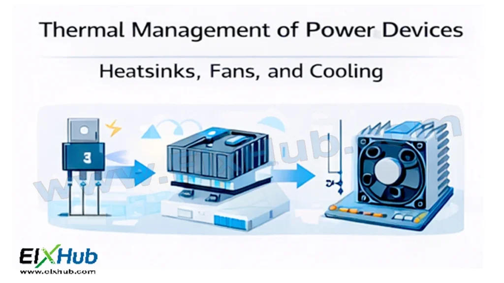
This article provides a comprehensive and practical guide to thermal management of power devices. It covers heat generation mechanisms, thermal resistance concepts, heatsinks, fans, forced and natural cooling, liquid cooling, thermal interface materials, design calculations, advantages and limitations, and real-world applications. Image placeholders are included to support visual understanding, and an image reference table is provided at the end for future content and SEO use.
Why Thermal Management Is Critical in Power Electronics
Power semiconductor devices are designed to operate within a specific temperature range known as the junction temperature limit. Exceeding this limit can lead to immediate failure or long-term reliability issues.
Key reasons thermal management is critical include:
- Preventing device overheating
- Maintaining electrical performance and efficiency
- Increasing device lifespan
- Avoiding thermal runaway
- Ensuring system safety and compliance
[Image Placeholder: Overheating effects in power electronic devices]
Even a small increase in junction temperature can significantly reduce the lifetime of a power device, making thermal design a core part of power electronics engineering.
Sources of Heat in Power Devices
Heat in power devices is generated primarily due to power losses. These losses can be broadly classified into conduction losses and switching losses.
Conduction Losses
Conduction losses occur when a device conducts current. They depend on:
- On-state resistance (MOSFETs)
- Forward voltage drop (diodes, IGBTs)
- Load current
Switching Losses
Switching losses occur during turn-on and turn-off transitions. They increase with:
- Switching frequency
- Voltage and current levels
- Switching speed
Other Heat Sources
Additional sources include:
- Gate drive losses
- Reverse recovery losses
- Parasitic resistances
[Image Placeholder: Heat generation in power semiconductor devices]
Basic Concepts of Heat Transfer
Understanding heat transfer mechanisms is essential for effective thermal management. There are three primary modes of heat transfer.
Conduction
Heat transfer through solid materials due to temperature gradients. This is the dominant mechanism inside power devices and heatsinks.
Convection
Heat transfer from a solid surface to a moving fluid such as air or liquid. This is the primary mechanism for heatsink cooling.
Radiation
Heat transfer through electromagnetic waves. Radiation plays a smaller role but becomes significant at high temperatures.
| Heat Transfer Mode | Medium | Importance in Power Electronics |
|---|---|---|
| Conduction | Solid materials | Very high |
| Convection | Air or liquid | High |
| Radiation | Vacuum or air | Moderate |
Thermal Resistance and Thermal Modeling
Thermal behavior of power devices is commonly analyzed using thermal resistance models, similar to electrical resistance.
Thermal Resistance Concept
Thermal resistance (Rθ) represents how easily heat flows from one point to another.
Key thermal resistances include:
- Junction-to-case (RθJC)
- Case-to-heatsink (RθCS)
- Heatsink-to-ambient (RθSA)
[Image Placeholder: Thermal resistance network of a power device]
Junction Temperature Calculation
The junction temperature can be estimated using:
Junction Temperature = Ambient Temperature + (Power Loss × Total Thermal Resistance)
Accurate thermal modeling ensures devices operate within safe temperature limits.
Heatsinks – The Primary Cooling Solution
Heatsinks are the most widely used thermal management components in power electronics. Their purpose is to increase surface area and improve heat dissipation.
Types of Heatsinks
| Heatsink Type | Description | Applications |
|---|---|---|
| Passive heatsink | No moving parts | Low to medium power |
| Active heatsink | Uses fan | Medium to high power |
| Extruded aluminum | Lightweight, low cost | General electronics |
| Bonded fin | Higher performance | Industrial systems |
| Skived fin | Very high surface area | High power density systems |
[Image Placeholder: Different types of heatsinks used in power electronics]
Heatsink Materials
Aluminum and copper are commonly used materials.
| Material | Thermal Conductivity | Advantages |
|---|---|---|
| Aluminum | Moderate | Lightweight, low cost |
| Copper | High | Excellent heat transfer |
Aluminum is preferred for most applications due to its balance of cost and performance.
Fans and Forced Air Cooling
When passive cooling is insufficient, forced air cooling using fans is employed. Fans significantly increase convection heat transfer.
Types of Fans
| Fan Type | Characteristics | Use Case |
|---|---|---|
| Axial fan | High airflow | General cooling |
| Centrifugal fan | High pressure | Dense heatsinks |
[Image Placeholder: Fan-assisted cooling in power electronics]
Advantages of Fan Cooling
- Improved heat dissipation
- Smaller heatsink size
- Higher power density
Limitations of Fan Cooling
- Noise
- Reduced reliability due to moving parts
- Dust accumulation
Liquid Cooling Techniques
For very high-power applications, air cooling becomes insufficient, and liquid cooling is used.
Types of Liquid Cooling
| Cooling Method | Description |
|---|---|
| Cold plate cooling | Liquid flows through metal plate |
| Immersion cooling | Devices submerged in coolant |
| Heat pipe cooling | Phase-change heat transfer |
[Image Placeholder: Liquid cooling system for power electronics]
Liquid cooling is widely used in EV powertrains, high-power inverters, and data center power supplies.
Thermal Interface Materials (TIMs)
Thermal interface materials are used to reduce thermal resistance between mating surfaces.
Common TIM Types
| TIM Type | Characteristics |
|---|---|
| Thermal grease | Low resistance, messy |
| Thermal pads | Easy to use |
| Phase change materials | Solid to liquid at temperature |
| Insulating sheets | Electrical isolation |
[Image Placeholder: Thermal interface materials used with power devices]
Proper selection of TIMs is crucial for effective thermal conduction.
PCB-Level Thermal Management
Printed circuit boards also play a role in heat dissipation.
Key PCB thermal techniques include:
- Thicker copper layers
- Thermal vias
- Heat spreading planes
- Metal-core PCBs
[Image Placeholder: PCB thermal management techniques]
These techniques are especially important in compact power electronics designs.
Thermal Design Considerations
When designing a thermal management system, engineers must consider:
- Ambient temperature
- Power dissipation levels
- Device mounting orientation
- Airflow direction
- Environmental conditions
Practical Thermal Design Steps
| Step | Description |
|---|---|
| Loss estimation | Calculate power losses |
| Device selection | Check thermal ratings |
| Cooling method | Choose air or liquid |
| Simulation | Perform thermal analysis |
| Testing | Validate under real conditions |
Applications of Thermal Management in Power Electronics
Thermal management is essential across many applications:
- Solar inverters
- Wind turbine converters
- EV traction inverters
- Motor drives
- Industrial power supplies
- UPS and data centers
[Image Placeholder: Thermal management in inverter systems]
Challenges and Future Trends
Challenges include higher power density, compact designs, and harsh environments. Future trends focus on:
- Advanced materials (SiC, GaN)
- Integrated cooling solutions
- Smart thermal monitoring
- AI-based thermal control
Conclusion
Thermal management is a fundamental pillar of reliable and efficient power electronics systems. As power devices handle increasing levels of current and voltage, managing heat effectively becomes just as important as electrical design. Heatsinks, fans, liquid cooling, thermal interface materials, and PCB-level techniques work together to ensure power devices operate within safe temperature limits.
A well-designed thermal management system improves efficiency, extends device lifespan, enhances system reliability, and prevents costly failures. As technology continues to evolve toward higher power density and compact designs, thermal management will remain a critical area of innovation and engineering excellence in power electronics.
Image Reference Table
| Filename | Description | Alt Text |
|---|---|---|
| overheating-devices.png | Effects of overheating in power devices | Power device overheating |
| heat-generation.png | Heat generation in power semiconductors | Heat in power electronics |
| thermal-resistance.png | Thermal resistance network | Thermal resistance model |
| heatsink-types.png | Types of heatsinks | Power electronics heatsinks |
| fan-cooling.png | Fan-assisted cooling system | Forced air cooling |
| liquid-cooling.png | Liquid cooling setup | Liquid cooling power electronics |
| tim-materials.png | Thermal interface materials | Thermal interface materials |
| pcb-thermal.png | PCB thermal management | PCB heat dissipation |
| inverter-cooling.png | Inverter thermal system | Power electronics cooling system |
SEO Title
Thermal Management of Power Devices – Heatsinks, Fans, and Cooling Techniques
Meta Description
Learn how thermal management protects power devices using heatsinks, fans, liquid cooling, and thermal design techniques for reliable power electronics systems.