Introduction
Ring counters and Johnson counters are special types of counters used in digital electronics that belong to the category of sequential circuits. Unlike simple binary counters that count in numerical order, these counters generate specific repeating patterns that are extremely useful in timing control, sequencing, state machines, and digital control systems. They are widely used in applications such as digital clocks, traffic light controllers, LED chasers, sequence generators, and control logic.
Both ring counters and Johnson counters are derived from shift registers with feedback, meaning the output of the last flip-flop is fed back to the input of the first flip-flop. Although their structures appear similar, their operation, number of states, and applications differ significantly. Understanding these counters helps build strong foundations in advanced digital electronics and prepares learners for complex system design.
This article provides a complete explanation of ring counters and Johnson counters, including working principles, state sequences, timing behavior, advantages, limitations, and practical applications.
What is a Ring Counter?
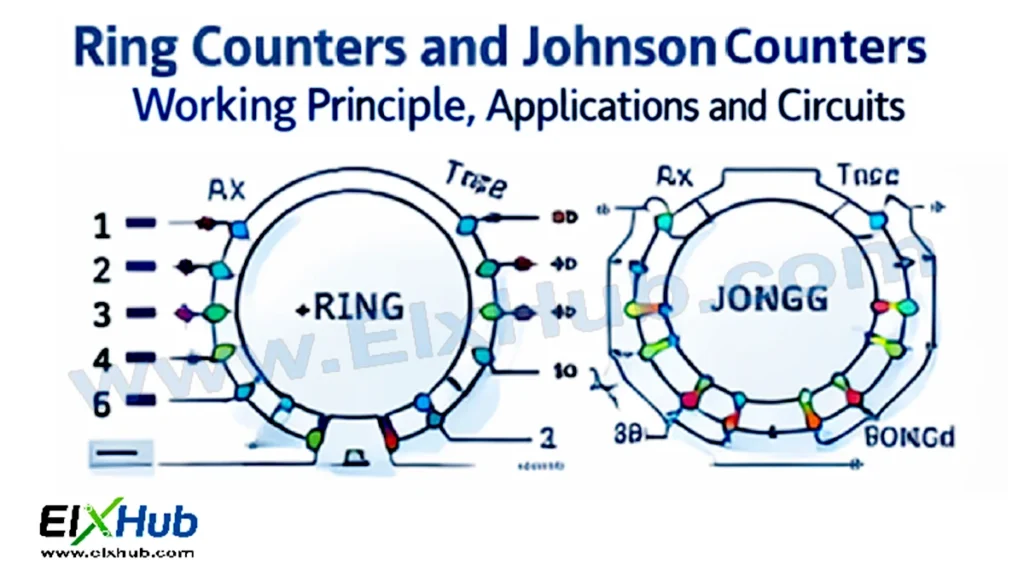
A ring counter is a type of counter formed by connecting a group of flip-flops in a shift register configuration with the output of the last flip-flop fed back to the input of the first flip-flop. In a ring counter, only one flip-flop is set to logic 1 at any time, while all others remain at logic 0.
As clock pulses are applied, the single logic 1 circulates or “rings” through the flip-flops, giving the counter its name.
Structure of a Ring Counter
A ring counter consists of:
A shift register made of flip-flops
A feedback connection from last output to first input
A common clock signal
An initial preset or reset circuit
At initialization, one flip-flop is set to 1 and all others are reset to 0.
Working of a Ring Counter
Consider a 4-bit ring counter using four D flip-flops.
Initial state:
1000
With each clock pulse, the logic 1 shifts to the next flip-flop.
State sequence:
1000
0100
0010
0001
1000
The sequence repeats indefinitely as long as clock pulses are applied.
Number of States in Ring Counter
For an n-bit ring counter:
Number of unique states = n
This is significantly fewer than a binary counter, which has 2ⁿ states.
Advantages of Ring Counters
Simple decoding
No complex logic required
Glitch-free outputs
High-speed operation
Because only one output is high at a time, ring counters are ideal for control and sequencing applications.
Limitations of Ring Counters
Requires preset or initialization
Inefficient use of flip-flops
Limited number of states
More hardware compared to binary counters
Applications of Ring Counters
LED chaser circuits
Sequence generators
Timing control systems
Digital clocks
Traffic light controllers
Stepper motor control
What is a Johnson Counter?
A Johnson counter, also known as a twisted ring counter, is a modified version of the ring counter. Instead of feeding the last output directly back to the first input, the inverted output of the last flip-flop is fed back to the input of the first flip-flop.
This small modification dramatically increases the number of usable states.
Structure of a Johnson Counter
A Johnson counter includes:
A shift register of flip-flops
An inverter in the feedback path
Common clock input
Reset circuitry
The inverted feedback allows the counter to cycle through a longer sequence of states.
Working of a Johnson Counter
Consider a 4-bit Johnson counter.
Initial state:
0000
With each clock pulse, the inverted last output is shifted into the first flip-flop.
State sequence:
0000
1000
1100
1110
1111
0111
0011
0001
0000
The sequence then repeats.
Number of States in Johnson Counter
For an n-bit Johnson counter:
Number of unique states = 2n
This makes Johnson counters more efficient than ring counters in terms of state utilization.
Comparison Between Ring Counter and Johnson Counter
| Feature | Ring Counter | Johnson Counter |
|---|---|---|
| Feedback | Direct | Inverted |
| States | n | 2n |
| Hardware efficiency | Low | Better |
| Complexity | Simple | Slightly complex |
| Decoding | Very easy | Easy |
Timing Behavior
Both counters are synchronous circuits and depend on clock signals.
Key timing aspects:
Clock frequency controls speed
Propagation delay affects output timing
Proper reset ensures correct sequence
Stable clock signals are critical for reliable operation.
ICs Used for Ring and Johnson Counters
| IC Number | Description |
|---|---|
| CD4017 | Decade Johnson counter |
| 74HC164 | Shift register (ring counter) |
| 74HC4015 | Dual shift register |
| 74LS194 | Universal shift register |
The CD4017 is one of the most popular Johnson counters and is widely used in hobby and industrial projects.
Johnson Counter as Decade Counter
A 5-bit Johnson counter produces 10 unique states, making it suitable for decimal counting. The CD4017 IC is a classic example, providing 10 decoded outputs from a single clock input.
Applications of Johnson Counters
Decade counters
Digital clocks
LED sequencing circuits
Frequency division
State machines
Timing control
Advantages of Johnson Counters
More states with same number of flip-flops
Easy decoding
Reliable and stable operation
Widely available ICs
Limitations of Johnson Counters
Requires proper reset
Invalid states possible due to noise
Not suitable for complex counting operations
Conclusion
Ring counters and Johnson counters are essential sequential circuits that provide predictable and easily decoded output patterns. While ring counters offer simplicity and reliability, Johnson counters improve efficiency by doubling the number of states. Their applications range from LED sequencing and timing control to digital clocks and industrial automation. Mastery of these counters strengthens understanding of sequential logic and prepares designers for advanced digital system development.
Image Reference Table
| Filename | Description | Alt Text |
|---|---|---|
| ring-counter-diagram.png | Ring counter block diagram | Ring counter |
| ring-counter-states.png | Ring counter state sequence | Ring counter states |
| johnson-counter-diagram.png | Johnson counter diagram | Johnson counter |
| johnson-counter-states.png | Johnson counter state sequence | Johnson counter states |
| cd4017-pinout.png | CD4017 Johnson counter IC | CD4017 IC |
SEO Title
Ring Counters and Johnson Counters Explained with Working and Applications
Meta Description
Learn ring counters and Johnson counters in digital electronics. Understand working principles, state sequences, ICs, advantages, and real-world applications.