Introduction
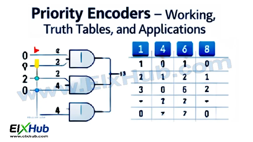
Priority encoders are an essential component of digital electronics, used to encode multiple input lines into binary code while prioritizing certain inputs over others. Unlike standard encoders, which treat all active inputs equally, priority encoders assign a predefined priority to each input, ensuring that the highest-priority active input determines the output. This feature is particularly important in complex digital systems, where multiple signals may arrive simultaneously and the system must decide which signal to process first.
Priority encoders are widely used in microprocessors, interrupt controllers, digital signal routing, and data compression systems. They form the backbone of many real-time decision-making circuits and play a key role in optimizing logic circuits. By understanding their working principle, truth tables, Boolean expressions, and real-world applications, electronics engineers and hobbyists can design reliable digital systems efficiently.
What is a Priority Encoder?
A priority encoder is a combinational circuit that produces a binary code corresponding to the highest-priority active input. Each input is assigned a priority level, typically with the highest-priority input given the lowest-numbered code. If multiple inputs are active at the same time, the encoder outputs the binary code of the input with the highest priority.
The output of a priority encoder typically consists of multiple bits, depending on the number of inputs. For example, a 4-to-2 priority encoder has four input lines and two output lines, producing a 2-bit binary code corresponding to the highest-priority input.
Difference Between Standard Encoder and Priority Encoder
| Feature | Standard Encoder | Priority Encoder |
|---|---|---|
| Input Priority | All inputs treated equally | Highest-priority input selected if multiple inputs active |
| Output | Binary code of any active input | Binary code of highest-priority input |
| Use Case | Simple encoding tasks | Real-time decision-making and interrupts |
| Complexity | Simple | Slightly complex |
Basic 4-to-2 Priority Encoder
A 4-to-2 priority encoder has four inputs (D0, D1, D2, D3) and two outputs (Y1, Y0). The highest priority is assigned to D3, followed by D2, D1, and D0. If multiple inputs are active, the output reflects the highest-priority active input.
Truth Table of 4-to-2 Priority Encoder
| D3 | D2 | D1 | D0 | Y1 | Y0 | Active Input |
|---|---|---|---|---|---|---|
| 0 | 0 | 0 | 1 | 0 | 0 | D0 |
| 0 | 0 | 1 | 0 | 0 | 1 | D1 |
| 0 | 0 | 1 | 1 | 0 | 1 | D1 |
| 0 | 1 | 0 | 0 | 1 | 0 | D2 |
| 0 | 1 | 0 | 1 | 1 | 0 | D2 |
| 0 | 1 | 1 | 0 | 1 | 0 | D2 |
| 0 | 1 | 1 | 1 | 1 | 0 | D2 |
| 1 | 0 | 0 | 0 | 1 | 1 | D3 |
| 1 | 0 | 0 | 1 | 1 | 1 | D3 |
| 1 | 0 | 1 | 0 | 1 | 1 | D3 |
| 1 | 0 | 1 | 1 | 1 | 1 | D3 |
| 1 | 1 | 0 | 0 | 1 | 1 | D3 |
| 1 | 1 | 0 | 1 | 1 | 1 | D3 |
| 1 | 1 | 1 | 0 | 1 | 1 | D3 |
| 1 | 1 | 1 | 1 | 1 | 1 | D3 |
| 0 | 0 | 0 | 0 | 0 | 0 | None |
Boolean Expressions
The Boolean expressions for the 4-to-2 priority encoder outputs Y1 and Y0 are derived from the truth table.
- Y1 = D3 + D2
- Y0 = D3 + D1
These expressions can be implemented using OR gates in a logic circuit.
8-to-3 Priority Encoder
For larger digital systems, an 8-to-3 priority encoder is commonly used. It has eight input lines and three output lines, producing a 3-bit binary code corresponding to the highest-priority input. Inputs are prioritized from D7 (highest) to D0 (lowest).
Truth Table for 8-to-3 Priority Encoder
| D7 | D6 | D5 | D4 | D3 | D2 | D1 | D0 | Y2 | Y1 | Y0 | Active Input |
|---|---|---|---|---|---|---|---|---|---|---|---|
| 0 | 0 | 0 | 0 | 0 | 0 | 0 | 1 | 0 | 0 | 0 | D0 |
| 0 | 0 | 0 | 0 | 0 | 0 | 1 | 0 | 0 | 0 | 1 | D1 |
| 0 | 0 | 0 | 0 | 0 | 1 | 0 | 0 | 0 | 1 | 0 | D2 |
| 0 | 0 | 0 | 0 | 1 | 0 | 0 | 0 | 0 | 1 | 1 | D3 |
| 0 | 0 | 0 | 1 | 0 | 0 | 0 | 0 | 1 | 0 | 0 | D4 |
| 0 | 0 | 1 | 0 | 0 | 0 | 0 | 0 | 1 | 0 | 1 | D5 |
| 0 | 1 | 0 | 0 | 0 | 0 | 0 | 0 | 1 | 1 | 0 | D6 |
| 1 | 0 | 0 | 0 | 0 | 0 | 0 | 0 | 1 | 1 | 1 | D7 |
Applications of Priority Encoders
- Interrupt Controllers:
Priority encoders are used in microprocessor-based systems to select which interrupt request to serve first when multiple devices request service simultaneously. - Digital Signal Selection:
In communication and control systems, priority encoders determine which signal gets transmitted when several are active. - Data Compression:
By encoding active inputs efficiently, priority encoders reduce the number of data lines required for transmission. - Keyboard Encoding:
In keyboards, priority encoders ensure that the highest-priority key pressed is registered first. - Control Systems:
They are used in automated control applications where multiple sensors may trigger actions, but the highest-priority event must be processed first.
Implementation in Logic Circuits
Priority encoders are typically implemented using a combination of OR, AND, and NOT gates. For a 4-to-2 encoder:
- Y1 = D3 + D2
- Y0 = D3 + D1
These outputs are connected to OR gates. Logic simplification can also be done using Karnaugh maps for larger encoders like 8-to-3 or 16-to-4.
Image Placeholder (Horizontal): 4-to-2 priority encoder logic circuit
Image Placeholder (Horizontal): 8-to-3 priority encoder block diagram
Advantages of Priority Encoders
- Resolves conflicts when multiple inputs are active
- Reduces the number of logic lines needed
- Simplifies circuit design in real-time systems
- Can be cascaded for larger input systems
Limitations
- Slightly more complex than standard encoders
- Requires careful priority assignment
- Hardware complexity increases with input size
Conclusion
Priority encoders are a critical building block in digital electronics. By assigning priority to inputs, these circuits make real-time decisions possible, ensuring that the highest-priority signal is always processed first. They are widely used in interrupt controllers, keyboard encoding, communication systems, and data routing applications. Understanding their working principle, truth tables, Boolean expressions, and practical applications is essential for designing reliable, efficient, and optimized digital circuits.
Image Reference Table (For Future Use)
| Filename | Description | Alt Text |
|---|---|---|
| 4to2-priority-encoder.png | 4-to-2 priority encoder logic circuit diagram | 4-to-2 priority encoder |
| 8to3-priority-encoder.png | 8-to-3 priority encoder block diagram | 8-to-3 priority encoder |
| priority-encoder-truth-table.png | Truth table of priority encoder | Priority encoder truth table |
| priority-encoder-applications.png | Applications of priority encoders | Priority encoder practical applications |
| priority-encoder-circuit.png | Boolean implementation using logic gates | Priority encoder logic gates diagram |
SEO for WordPress (paste at the end in your SEO plugin):
SEO Title
Priority Encoders in Digital Electronics | Working, Truth Tables & Applications
Meta Description
Learn priority encoders in digital electronics. Understand working, truth tables, Boolean expressions, circuits, and practical applications for real-time systems.